
Table of contents: Removal and installation the lower… ↓ Removal and installation the upper… ↓ Removal and installation the oil… ↓ Removal and installation the oil… ↓ Removal and installation the PCV… ↓ Removal and installation the… ↓ Removal and installation of the… ↓
1. The installation details of the lubrication system components are shown in the illustration and also on illustrations 13.1a, 13.1d.
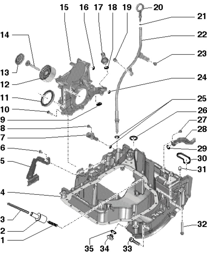
23.1. Installation details of the upper section of the oil pan:
1 - Spring;
2 - Clutch;
3 - Oil pump drive shaft;
4 - Upper section of the oil pan;
5 - Electrical wiring bracket;
6, 8, 10, 19, 23, 27 - Bolt, 9 Nm;
7 - Valve "N428" for regulating oil pressure; accessible after removing the front soundproofing panel under the engine compartment;
9 - Sealing elements, 2 pcs.;
11 - Front crankshaft oil seal;
12 - Right intermediate roller of the drive belt;
13 - Roller plug 12;
14 - Bolt, 23 Nm;
15 - Front sealing flange;
16, 21, 24, 25, 29 - O-ring, subject to replacement;
17 - D/V "F22" engine oil pressure (2-pin, with gray insulation), 20 Nm; accessible after removing the front soundproofing panel under the engine compartment;
18, 26, 30, 35 - Gasket, subject to replacement;
20 - Oil dipstick;
22 - Oil dipstick guide tube;
28 - Return oil pipe;
31 - Centering sleeve, 2 pcs.;
32 - Bolt, 5 Nm, then 15 Nm;
33 - Lower bolts for fastening the AT to the engine, 45 Nm;
34 - Service hole plug, 35 Nm.
2. Engine oil level and temperature sensor (4 in illustration 13.2) is secured to the lower section of the oil pan with three nuts (1), tightened to 9 Nm. After removing the sensor, its gasket (2) should be replaced.
3. Removal/installation of the oil pump is carried out in the same way as on 3.0 TDI engines of the 1st generation (see Section 13).
Removal and installation the lower section of the oil pan
4. Remove the left coolant pipe (see Chapter 3) and anti-roll bar (see Chapter 9).
5. Remove the drive belt and its tensioner (see Section 6). Remove the air cleaner (see Chapter 4).
6. Follow the steps in paragraphs 5-14 Section 13.
Removal and installation the upper section of the oil pan
7. Remove all timing chain covers (see Section 19) and the auxiliary drive chain (see Section 20).
8. Remove the front sealing flange (see Section 18) and oil pump (see Section 13).
9. Follow the steps in paragraphs 21-25 Section 13.
Removal and installation the oil cooler
10. Remove the EGR cooler (see Chapter 4).
11. Give the nut (1 in illustration 13.31) and slightly turn the upper coolant pipe in the direction of the arrow.
12. Unscrew the bolts (1-4 in illustration 13.32b) and remove the oil cooler, collecting the leaking oil with a cloth.
13. Installation is carried out in reverse order. Use new sealing elements. Finally, check the engine oil level (see Chapter 1).
Removal and installation the oil filter housing
14. Remove the EGR activator (see Chapter 4).
15. Unscrew the bolt (see illustration) and remove the oil supply line.
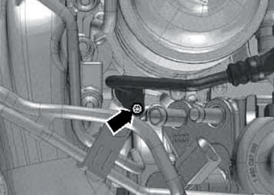
23.15. Oil supply line bolt.
16. Remove the oil filter element (see Section 6 of Chapter 1).
17. Unscrew the bolt (1 in illustration 3.3) and a hollow bolt (3) for fastening the oil supply line to the turbocharger.
18. Remove the bolts (see illustration 13.47) and remove the holders using a magnet.
19. Make loops from two plastic ties (2 and 3 in illustration 13.40) and secure them to the filter housing groove using the third clamp (1). Pull the hinges and remove the oil filter housing.
20. Installation is carried out in reverse order. Use new seals, a new filter element and fresh oil.
Removal and installation the PCV pressure control valve
21. Lower the EGR radiator (see Chapter 4).
22. Disconnect the PCV hose from the PCV valve (arrow in illustration 13.52), unscrew the two bolts (1 and 2) and remove the PCV valve.
23. Installation is carried out in reverse order. Use new sealing elements.
Removal and installation the mounting plate
24. Bleed the upper coolant pipe (see Chapter 3) and PCV pressure control valve (see subsection above).
25. Disconnect the connector D/V "F378" of the low pressure engine oil (see illustration 13.65).
26. Remove the bolts (arrows in the illustration) and remove the mounting plate together with the oil cooler, PCV valve and oil filter housing installed on it.
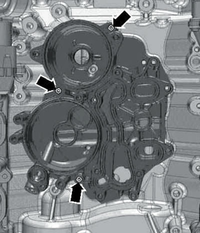
23.26. Mounting plate fastening.
27. Installation is carried out in reverse order. Use new sealing elements. Tighten the mounting plate bolts in a diagonal pattern, starting from the inside and working outward. Finally, fill the engine oil (see Chapter 1).
Removal and installation of the low-pressure engine oil control valve "F378"
28. Remove the "V400" EGR cooler pump (see Chapter 4).
29. Disconnect the coolant hose (2 in the illustration) and take it aside.
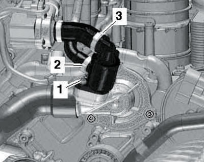
23.29. Coolant hose clamp (2).
30. Disconnect the connector D/V "F378" of the low pressure engine oil (see illustration 13.65) and unscrew this D/V using a 24 mm extended head with a hinge.
31. Installation is carried out in reverse order. Use new D/V gasket "F378".