Repair Chevrolet Repair Toyota Repair Honda Repair AvtoVAZ Repair Mercedes-Benz Repair BMW Repair Opel
Home  |  Contacts  |  Sitemap  |    
English Русский
Български
Беларускі
Український
Српски
Hrvatski
Română
Polski
Slovenský
Magyar
AudiManual.ru


  • AUDI 80
  • AUDI 100
  • AUDI A3
  • AUDI A4
  • AUDI A6
  • AUDI A8
  • AUDI Q
  • OTHER
  • ARTICLES
Q7 Typ 4L (2005-2015, diesel) Q5 Type 8R (2008-2017)

Work on the gas distribution mechanism (Audi Q7-4L-D)

  • Home
  • Audi Q
  • Q7 Typ 4L (2005-2015, diesel)
  • Power unit
  • Diesels 3.0 l (CATA, CCMA)
  • Work on the gas distribution mechanism
            0
Table of contents: Replacing camshaft seals ↓ Removal and installation the… ↓ Removal and installation the… ↓ Checking hydraulic compensators ↓ Replacing valve stem seals ↓
Caution: After installing the camshafts, wait at least 30 minutes before starting the engine to allow the hydraulic lifters to settle. Otherwise, the valves may hit the pistons.


1. Timing belt component installation details are shown on illustrations 12.1 using the example of the left cylinder head.

2. Processing of valves and their seats, except for lapping, is not permitted.

3. When working with the timing belt, arrange the removed parts so that they can then be installed in their original places.

Replacing camshaft seals


4. Remove the upper section of the intake manifold (see Chapter 4).

5. Follow the steps in paragraphs 4-8 Section 12.

Removal and installation the camshafts of the left cylinder head


Note: Special tools are required to install the camshafts.


6. Remove the left upper timing chain from the camshafts (see Section 9).

7. Remove the upper section of the intake manifold (see Chapter 4).

8. Remove the fuel injection pump drive toothed belt (see Chapter 4) and the camshaft gear (see paragraphs 9-10 of Section 11).

9. Remove the left cylinder head cover (see Section 11).

10. Remove the valve from the bracket (1 in the illustration) "N345" EGR cooler.

22.10. Valve «N345» (1), wiring harness (3), bolt (4) and pin (2) for fastening the upper engine…

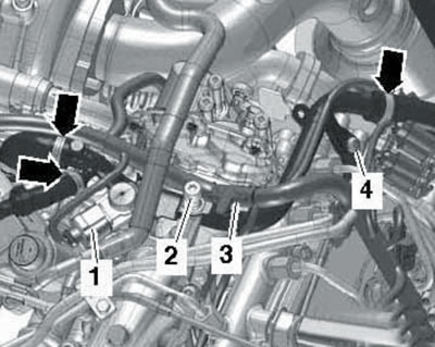
22.10. Valve "N345" (1), wiring harness (3), bolt (4) and pin (2) for fastening the upper engine cover.


Remove the bolt (4) and mounting pin (2) of the upper engine casing. Move the wiring harness (3) from the upper left coolant pipe to the side.

11. Remove the union nut (1 in illustration 12.13) high-pressure fuel line, unscrew the bolts (arrows) and remove the fuel distribution line from the left cylinder head.

12. Follow the steps in paragraphs 14-24 Section 12.

Removal and installation the camshafts of the right cylinder head


Note: Special tools are required to install the camshafts.


13. Remove the right upper timing chain from the camshafts (see Section 9).

14. Remove the right cylinder head cover (see Section 11).

15. Follow the steps in paragraphs 29-39 Section 12.

Checking hydraulic compensators


Note: Maintenance of hydraulic compensators is not provided. Valve noise immediately after starting the engine does not indicate a malfunction.


16. Start the engine and wait until the coolant temperature rises to approximately 80°C. Increase the engine speed to 2500 rpm for approximately 2 minutes. If necessary, take a test drive.

17. If the hydraulic lifters continue to make noise after this, determine which of them are faulty as described below.

18. Remove the corresponding cylinder head cover (see Section 11). On models before 05.2010, disconnect the air hose (see illustration 17.7)

19. Insert the guide pin with a smaller diameter (2 in illustration 4.73a) into the T40058 adapter. Using this adapter, turn the crankshaft clockwise (see illustration 13.74b) so that the cam for the hydraulic compensator being tested is facing upwards.


20. Press the rocker arm (see illustration 12.44) and determine the gap between the cam and the hydraulic compensator: if it is possible to insert a 0.20 mm thick feeler gauge into this gap, replace the hydraulic compensator (see the subsection "Removing and installing camshafts" above).

21. After checking, install the cylinder head cover and air hose.

Replacing valve stem seals


22. Replacing the valve stem seals is done in the same way as on 1st generation 3.0 TDI engines (see Section 12).

[This publication is borrowed from the resource: AUDIMANUAL.RU]
The article was checked by auto expert Daniil Ushakov
This article is available at russian, bulgarian, belarusian, ukrainian, serbian, croatian, romanian, polish, slovak, hungarian

Share information:
Previous articles
Audi Q Q7 Typ 4L: Diesels 3.0 l (CATA, CCMA)
Next articles

Removal and installation cylinder heads and their covers
Removal and installation of timing chains, balance shaft and…
Removal and installation timing chain covers
Removal and installation the drive disc and crankshaft seals
Work with the lubrication system


Similar articles on other Audi car models:
Gas distribution mechanism drive Audi 80 B3 (1986-1991)
Hood lock mechanism Audi 100 C3 (1982-1990, diesel)
Removal and installation the locking mechanism Audi A3 Type 8L (1996-2003)
Torsen distribution differential Audi A4 B5 (1994-2001, petrol)
Timing belt for gas distribution mechanism drive — design… Audi A6 C5 Allroad (1999-2005)
Valve mechanism Audi A8 D2 (1994-2002)
Valve mechanism repair Audi A2 (1999-2005)
Link to this page in different formats


Visitor comments

No comments yet


How much will 18 + 16 =


Q7 4L(2005-2015, diesel) 
  • General information
  • Operating instructions
  • Maintenance
  • Power unit
  • Diesels 3.0 l (BUG, BUN, CAS)
  • Diesels 3.0 l (CATA, CCMA)
  • Diesels 3.0 l (CJGA/CJGC)
  • Diesels 4.2 l (BTR, CCFA/CCFC)
  • Cooling system
  • Fuel and exhaust system
  • Engine management system
  • Starting and charging
  • Transmission
  • Automatic gearbox
  • Drive shafts
  • Chassis
  • Brake system
  • Front suspension
  • Rear suspension
  • Steering system
  • Body
  • Air conditioner
  • Exterior
  • Interior
  • Electrical equipment
  • Equipment and devices
  • Electrical circuits
 
Q5 8R(2008-2017) 
  • General information
  • User manual
  • Power unit
  • Petrol engine 2.0 l
  • Petrol engine 3.2 l
  • Fuel system (petrol)
  • Diesel 2.0 liter (CA)
  • Diesel 2.0 liter (CG/CJ/CM)
  • Diesel engine 3.0 l
  • Fuel system (diesel)
  • Transmission
  • Manual gearbox 0B1
  • Manual gearbox 0B2
  • Automatic gearbox 0B5
  • Automatic gearbox 0B6
  • Chassis
  • Front suspension
  • Rear suspension
  • Brake system
  • Steering
  • Body
  • Exterior
  • Interior
  • Doors, locks and windows
  • Safety system
  • Ventilation and heating
  • Electrical equipment
  • Power devices
  • Equipment and devices
  • Lighting and alarm
  • Audio system
  • Electrical circuits
 
AudiManual.ru © 2017-2026 · Mobile version · Feedback · Sitemap: EN BG BY UA RS HR RO PL SK HU · Site search · News and articles
80 B2 · 80 B3 petrol · 80 B3 · 80 B4 · 100 C3 diesel · 100 C3 petrol · 100 C3 · 100 C4 petrol · 100 C4 · A3 Type 8L · A4 B5 petrol · A4 B5 · A4 B6 petrol · A4 B6 · A4 B7 · A4 B8 · A6 C4 · A6 C5 · A6 C5 Allroad · A8 D2 · Q5 Type 8R · Q7 Typ 4L · Audi A2 ·
This site uses cookies 🍪. Click the button to accept this fact.