
Table of contents: Transfer case 0AQ ↓ Transfer case 0BU ↓
Transfer case 0AQ
1. Raise the car (see Introduction).
2. Remove the rear sound insulation panel under the engine compartment (see Section 19 of Chapter 1).
3. On models with a 4.2L engine, disconnect the exhaust system at the clamps (1 and 2 in Illustration 35.32 Chapter 2).
Note: Do not bend the flexible sections of the exhaust system more than 10°.
4. On models with a 4.2 L engine with a diesel particulate filter, unscrew the bolts securing the left and right diesel particulate filters to the AT support and to the body: (1 and 2 in Illustration 35.33 Chapter 2) And (4 and 5 in illustration 35.34 Chapter 2).
5. Remove the bolts (1 in the illustration) fastening the rear propeller shaft to the transfer case, holding the shaft from turning using the T10172 device with T10172/6 adapters.
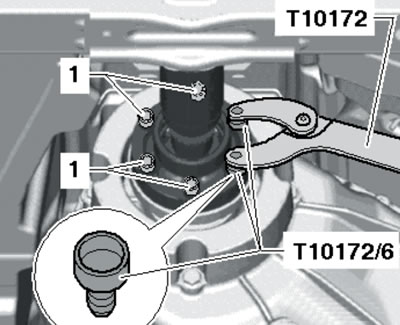
2.5. Fastening the rear propeller shaft to the transfer case.
Tie the rear propeller shaft to the body.
6. Remove the bolts (see illustration 4.65 Chapter 2) fastening the front propeller shaft to the transfer case, holding the shaft from turning using T10172 devices with T10172/6 adapters. Lightly compress the front propeller shaft by pressing it forward (the hinges allow the shaft to be moved in the axial direction). Tie the front propeller shaft to the body.
7. Remove the bolts on the particulate filter bracket (see illustration 4.58a in Chapter 2).
8. Secure the T40091/5 adapters (on the left side) and T40091/4 (on the right side), screwing in the bolts (And in the illustration) M10x30 into the front threaded holes (B) in the body by hand.
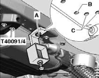
2.8. Installing adapter T40091/4.
9. Slide the adapter T40093/6 onto the crossbar T40091/1, slide the crossbar onto the adapters T40091/4 and T40091/5 and secure with bolts (arrows in the illustration).
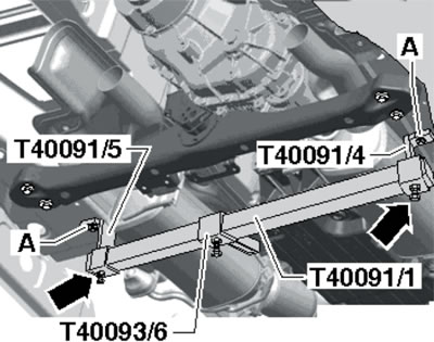
2.9. Installing the crossbar.
After this, tighten the adapter mounting bolts (A) to 30 Nm.
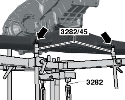
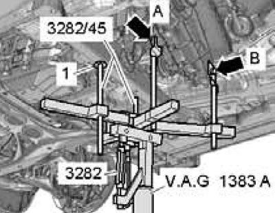
10. Install support #3282 on the transmission jack with the smaller pin (arrow in the illustration) in the direction of movement.
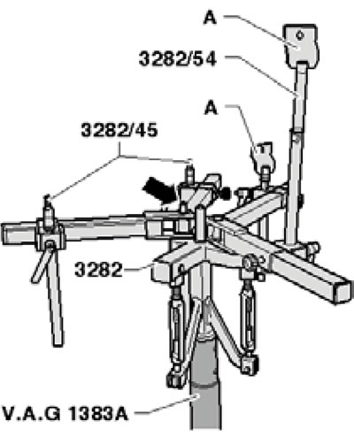
2.10. Lifting devices.
Install pins No. 3282/45, No. 3282/54 and support (A) as shown in the illustration.
11. Secure the support to the transfer case with an M10x25 bolt and nut (And in the illustration), and also at the top point of the outlet flange with an M10x20 bolt and nut (B).
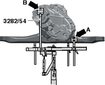
2.11. Fastening the support to the transfer case.
12. Secure the support to the AT support with M8 nuts (arrows in the illustration).
2.12. Fastening the support to the AT support.
13. Remove the bolts (1 and 2 in Illustration 4.43 Chapter 6) AT supports.
14. Lower the transfer case on the jack to a distance (and in the illustration) approximately 50 mm.
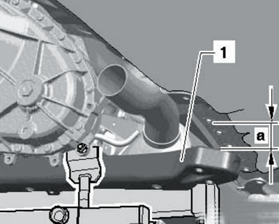
2.14. Dimension for lowering the transfer case.
15. Insert the T40091/6 spindle with the T40091/7 square nut into the T40093/6 adapter (see illustration).
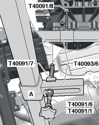
2.15. Fixing the transfer case.
Place the -/6 spindle against the AT housing, placing the T40091/8 spacer between them, and then tighten the lock nut (A) so that the spindle does not turn.
16. Remove the bolts (1 and 2 in the illustration) fastenings of the transfer case to the AT and pull the transfer case away.
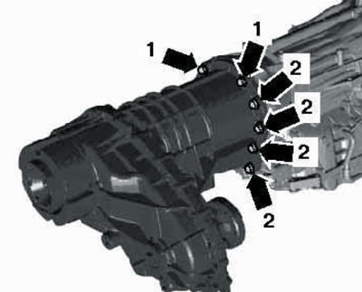
2.16. Fastening the transfer case on the AT.
17. If the transfer case is to be replaced, remove the AT support (arrows in the illustration) and its bracket (1 and 2).
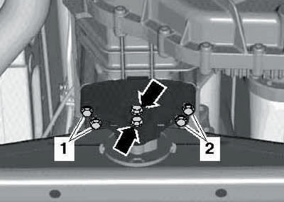
2.17. Fastening the AT support to the transfer case.
18. When further disassembling/assembling the transfer case, follow the instructions. illustrations.
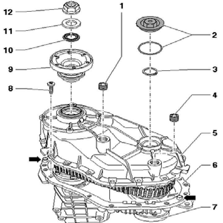
2.18a. Transfer case cover installation details:
1 - Filler plug, 25 Nm;
2 - Plug assembly with sealing ring, 18 Nm;
3 - Retaining ring;
4 - Drain plug, 25 Nm;
5 - Transfer case cover;
6 - Transfer case housing;
7 - Flange for front propeller shaft;
8 - Bolts, 16 pcs., 28 Nm;
9 - Flange for rear propeller shaft;
10 - Washer, subject to replacement;
11 - Washer;
12 - Nut, 320 Nm, must be replaced.
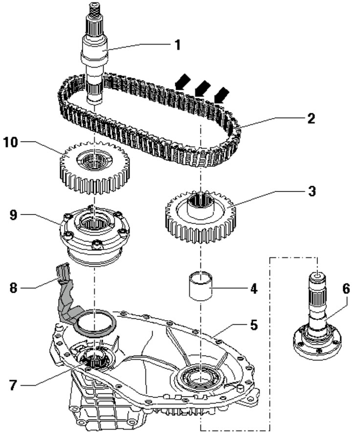
2.18b. Installation details of the output shaft, chain, sprockets and center differential:
1 - Output shaft, for rear propeller shaft;
2 - Chain, colored links facing the lid;
3 - Sprocket for front propeller shaft;
4 - Spacer sleeve;
5 - Transfer case housing;
6 - Front propeller shaft flange;
7 - Input shaft;
8 - Oil collector;
9 - Limited-slip center differential, serviceable only at the factory;
10 - Sprocket for rear propeller shaft.
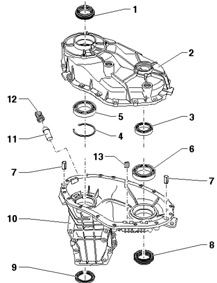
2.18s. Transfer case cover and housing assembly parts 0AQ:
1 - Flange seal for rear propeller shaft;
2 - Transfer case cover;
3 - Small ball bearing of the front propeller shaft flange;
4 - Bearing retaining ring 5;
5 - Large ball bearing of the rear propeller shaft flange;
6 - Large ball bearing of the front propeller shaft flange;
7 - Centering sleeve, inserted into the crankcase;
8 - Flange seal for front propeller shaft;
9 - Input shaft seal;
10 - Transfer case housing;
11 - Breather bushing;
12 - Breather valve;
13 - Magnet.
19. Installation is carried out in reverse order. Before installation, ensure the centering pins are present in the automatic transmission. Use new bolts to secure the transfer case to the automatic transmission, tightening them to 45 Nm.
Transfer case 0BU
20. The installation details of the 0BU transfer case are shown in the illustration.
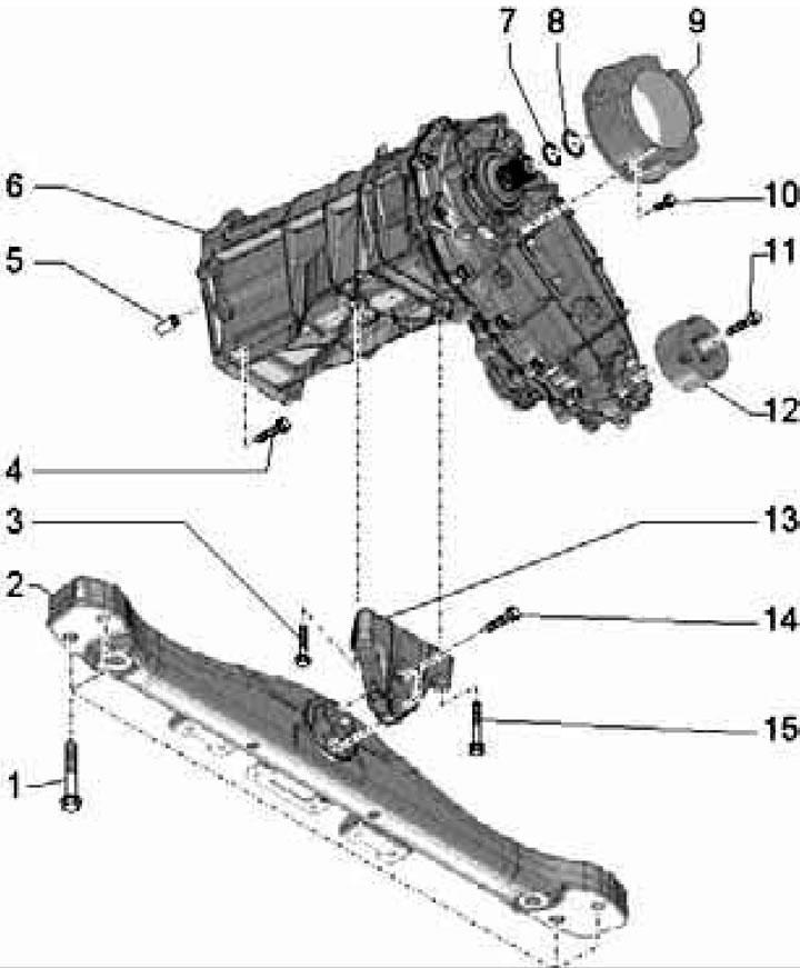
2.20. Transfer case 0BU installation details:
1, 4, 14 - Bolt, to be replaced, 50 Nm, then tighten to an angle of 90°;
2 - AT support;
3, 15 - Bolt, 20 Nm;
5 - Centering sleeve, 2 pcs.;
6 - Transfer case;
7 - Sealing ring (green, diameter 28 mm), subject to replacement;
8 - Retaining ring (silver, diameter 28 mm), subject to replacement;
9, 12 - Damping weight;
10 - Self-locking bolt, replaceable, 32 Nm;
11 - Self-locking bolt, replaceable, 50 Nm;
13 - AT support bracket.
21. Remove the rear propeller shaft (see Section 5).
22. Remove the rear sound insulation panel under the engine compartment (see Section 19 of Chapter 1).
23. Disconnect the AT wiring connectors (1-3 in illustration 4.48 Chapter 2).
24. Remove the bolts on the particulate filter bracket (see illustration 4.58a in Chapter 2). On 4.2L engines, perform this step on both sides.
25. Remove the bolts (see illustration 4.65 Chapter 2) fastening the front propeller shaft to the transfer case, holding the shaft from turning using T10172 devices with T10172/6 adapters. Tie the front propeller shaft to the body.
26. Slide the adapter T40093/6 onto the crossbar T40091/1, slide the crossbar onto the adapters T40091/4 and T40091/5 and secure with bolts (arrows in illustration 2.9). After this, tighten the adapter mounting bolts (A): on the left side - bolt M10x30 with a force of 30 Nm, and on the right side - bolt M8x30 with a washer with a force of 23 Nm.
27. Secure the support to the transfer case with M8x20 bolts (And in the illustration) and M10x20 (B).
2.27. Installation of the support.
Secure bolt #3282/45 to the AT support on the right with an M8 nut. On the left, press bolt #3282/45 with a washer (1) against the AT support.
28. Follow the steps described in paragraphs 13-17.
29. Installation is carried out in reverse order. Before installation, make sure that the centering pins are present in the AT and lubricate the splines of the transfer case input shaft with G 000 100 grease.
The original article is available on the online resource AudiManual