
Table of contents: Replacing the tie rod end ↓ Complete replacement of the steering… ↓
Replacing the tie rod end
A tie rod puller is required here. The tie rod end cannot be simply pulled out of the control arm after the bolt has been loosened; it is inserted with the so-called responsibility cone. The conical formations in the tie rod end and the control arm fit tightly into each other and can then no longer be separated without an auxiliary means.
You are already familiar with the puller from the first time you removed the shock absorber:
Remove the wheel.
Unscrew the self-locking nut in the tie rod end.
Use a puller to pull the tie rod end upwards from the control arm.
Loosen the lock nut on the steering linkage rod, while supporting the hex bolt.
Mark the position of the screw-in depth of the tie rod end so that during assembly it is clear how much the new end needs to be screwed in.
Unscrew the tie rod end and screw in a new one up to the mark.
Press the ball-head bolt of the tie rod end into the control arm, and tap it gently if necessary.
Tighten the new self-locking nut to 50 Nm.
Tighten the tie rod nuts to 50 Nm, making sure that the tie rod ends do not move forward or backward.
Check the alignment.
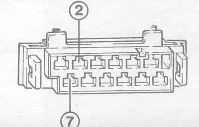
Checking the power supply of the power amplifier control unit. Voltage from the battery is supplied between the connection points 2 and 7 of the control unit indicated here when the ignition is on. If this does not happen, the fuse or wiring is faulty. Further testing should be carried out at a car repair shop.
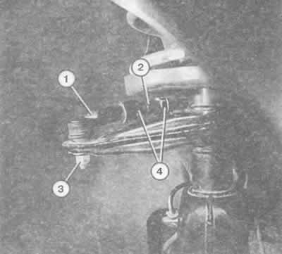
Shown here is the tie rod end (1) with the self-locking nut (3), the hexagonal threaded adjusting rod (2), and both lock nuts (4) used to secure the steering column (stalls) position of the transverse steering rod.
Complete replacement of the steering linkage
Buy new self-locking nuts.
Separate the tie rod end from the control arm as described in the previous section.
In the engine compartment, unscrew the steering linkage rod from the drive control mount.
Additionally: loosen the vertically stable panel fastening.
When screwing on new steering linkage rods, pay attention to their position.
In the middle (in drive control): the bend points in the direction of travel.
The central rod of the steering trapezoid should be bent downwards in the middle.
Tie rod end, outside: bend must be in direction of travel.
Tighten the steering linkage rod in the drive control mount with a force of 60 Nm.
Tighten the control panel rod mount to 40 Nm.
Pay attention to the fact that the tips of the transverse tie rod do not deviate either forward or backward. Otherwise, loosen the contour nuts in the cross tie rod tip and align the cross tie rod tip.
Tightening torque of lock nuts: 50 Nm. Tightening torque of the end of the transverse steering rod in the control arm: also 50 Nm.
Check the alignment.