
Table of contents: Removal ↓ Installation ↓
Removal
The steering gear is removed together with the steering rods and the steering gear shock absorber.
Before disconnecting the battery, find out if you have a radio activation code.
Turn off the ignition and disconnect the ground wire from the battery.
Set the wheels to drive straight ahead and remove the key from the ignition. Gently rock the steering wheel from side to side to lock it steering column.
Using a screwdriver blade, pry off the decorative trim from the steering column covers.
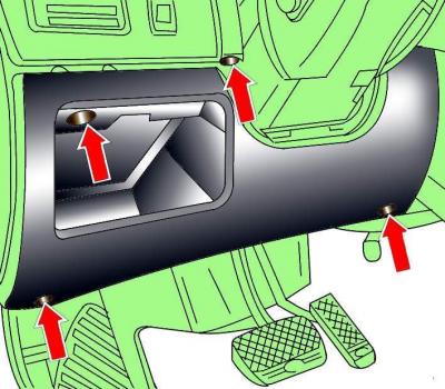
Fig. 14–4. Location of screws for fastening the decorative lower trim under the instrument panel on the driver's side
Remove the screws securing the decorative lower trim panel under the instrument panel on the driver's side (see Fig. 14-4).
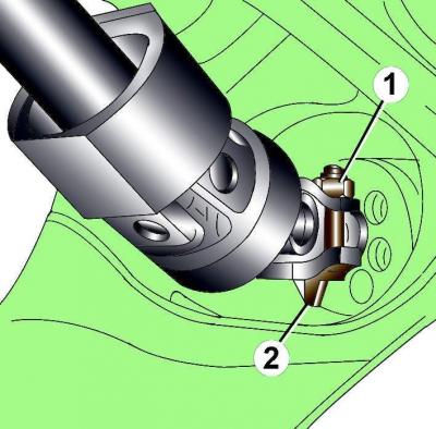
Fig. 14–8. Location of the nut (1) and clamp (2) for fastening the universal joint of the steering column
Unscrew nut 1 (see Fig. 14–8) securing the universal joint of the steering column.
Loosen the eccentric bolt by turning it clockwise and remove it.
Loosen the steering column mounting bolts.
Remove the steering column universal joint from the steering gear shaft by moving it downward.
Remove the steering shaft seal from inside the vehicle.
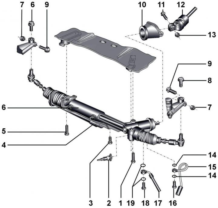
Fig. 14–11. Steering mechanism: 1 – combination bolt, 70 Nm; 2 – Servotronic electrical connector; 3 – cylindrical head bolt, 12 Nm; 4 – steering shock absorber; 5 – combination bolt, 70 Nm; 6 – power steering gear; 7 – self-locking nut, 50 Nm; 8 – combination bolt, 7 Nm; 9 – bolt; 10 – protective cover; 11 – eccentric bolt; 12 – steering column; 13 – self-locking nut, 40 Nm; 14 – sealing rings; 15 – pressure hose; 16 – hollow bolt, 40 Nm; 17 – return hose; 18 – hollow bolt, 50 Nm; 19 – sealing rings
Loosen the front wheel mounting bolts, lift the front of the car and secure it on stands. Remove the front wheels.
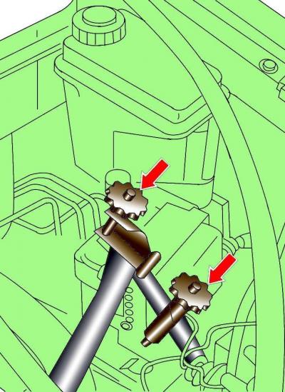
Fig. 14–12. Using 3094 Clamps to Clamp Power Steering Hydraulic Supply and Return Hoses
Using clamps 3094, clamp the power steering hydraulic supply and return hoses (Fig. 14–12).
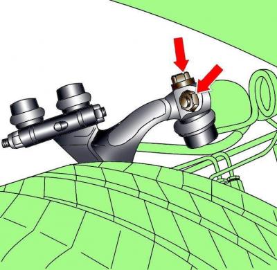
Fig. 14–13. Location of the bolts securing the steering rod to the steering knuckle
Unscrew the bolts securing the steering rods to the steering knuckles and push the steering rods down (Fig. 14–13).
On vehicles with V6 TDI diesel engines, remove the engine heat shields that block access to the steering gear mounting bolts.
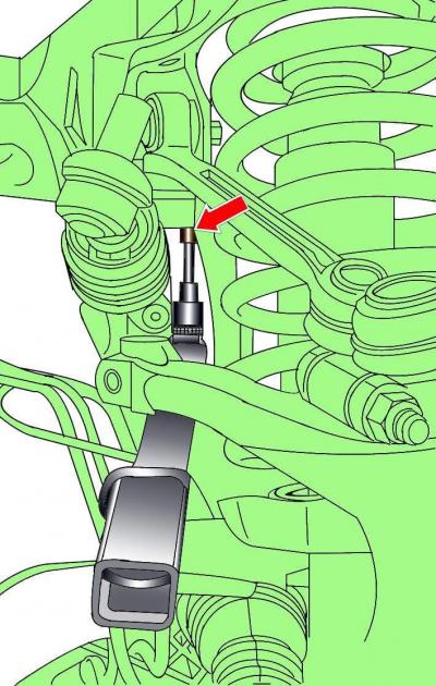
Fig. 14–14. Location of the steering gear mounting bolt on the right side of the vehicle
On the right side of the vehicle, unscrew the steering gear mounting bolts (Fig. 14–14). To make it easier to access the bolt, remove the fuel line from the holder and move it to the side.
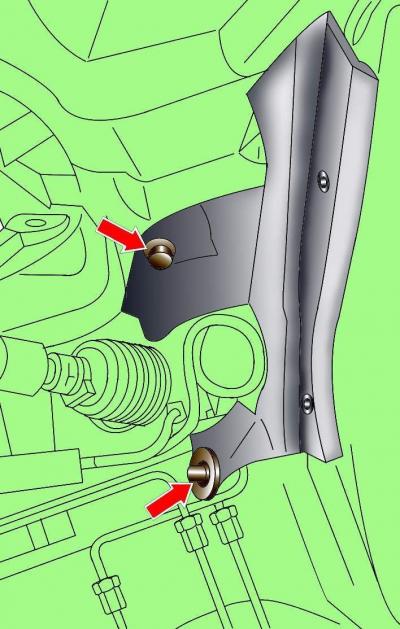
Fig. 14–15. Location of the part of the casing covering the wheel arch on the left side of the vehicle
On the left side of the car, unscrew the bolts and remove the part of the casing that covers the wheel arch (Fig. 14–15).
Place a container under the steering gear to collect any leaking fluid.
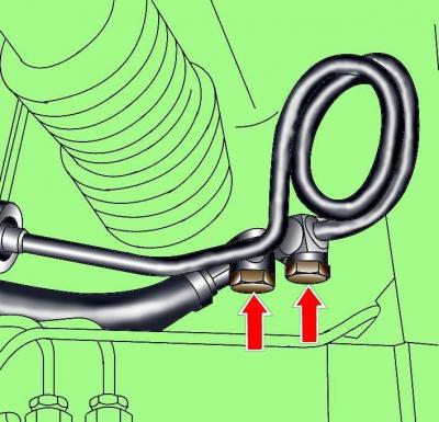
Fig. 14–16. Location of bolts securing the pressure and return hoses of the hydraulic power steering system to the steering gear
Unscrew the pressure and return hoses of the hydraulic power steering system from the steering gear through the wheel arch (Fig. 14–16).
If present, disconnect the electrical connector from the Servotronic valves.
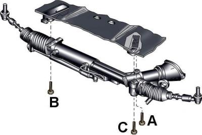
Fig. 14–17. Location of steering gear mounting bolts
Unscrew the two bolts securing the left side of the steering gear through the wheel arch (Fig. 14–17).
Disconnect the steering gear from the locking mechanism on the back of the storage chamber.
Remove the steering gear from the vehicle through the wheel arch.
Installation
When installing, it is necessary to use new nuts, sealing rings and clamps.
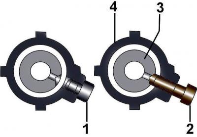
Fig. 14–19. Fixing the steering rack with the VAG 1907 installation tool: 1 – threaded plug, 12 Nm;
2 – VAG 1907 installation tool; 3 – rack; 4 – steering gear housing
Before installing the steering gear, set the rack to the middle position, unscrew the threaded plug and manually screw in the VAG 1907 installation tool in its place (see Fig. 14–19).
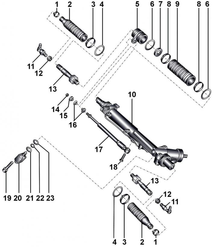
Fig. 14–20. Steering mechanism: 1 – clamp; 2 – protective cover; 3 - clamp; 4 – sealing ring; 5 – steering gear shock absorber holder; 6 – sealing ring; 7 – disc washer; 8 – clamp; 9 – protective cover; 10 – steering gear housing; 11 – steering rod end; 12 – nut, 40 Nm; 13 – inner connection of steering rod, 100 Nm; 14 – nut, 10 Nm; 15 – bushing; 16 – rubber bushings; 17 – steering shock absorber; 18 – bolt, 40 Nm; 19 – bolt, 3 Nm; 20 – Servotronic solenoid valve N119; 21, 22 – sealing rings; 23 – mesh filter
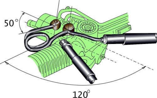
Fig. 14–18. Location and freedom of movement of hydraulic hoses of the steering gear before installation on the vehicle
Check the freedom of movement and position of the steering gear hoses (Fig. 14–18).
Install the steering gear and secure it with the locking mechanism on the back of the storage chamber.
Secure the steering gear with bolts, tightening them in sequence A, IN and WITH torque of 70 Nm (see Fig. 14–17).
Release the steering column adjustment mechanism and set it to a position close to horizontal.
Install the universal joint on the steering shaft, insert the eccentric bolt, turn it counterclockwise, screw the nut onto the bolt and tighten it to a torque of 40 N·m (see Fig. 14–8).
Unscrew the VAG 1907 installation tool, screw the threaded plug into the steering gear instead and tighten it to a torque of 12 Nm (Fig. 14–19).
Further installation is carried out in the reverse order of removal, taking into account the following.
Add fluid to the power steering hydraulic system and bleed air from it.
Check the power steering hydraulic system for leaks.
Check it out front wheel alignment angles.
Connect the ground wire to the battery.
Turn on radio and enter the code into it.
Raise the power windows all the way up. Then press all power window switches again for at least 1 second to the closed position to activate the power window control unit.
Set the time on the clock.