
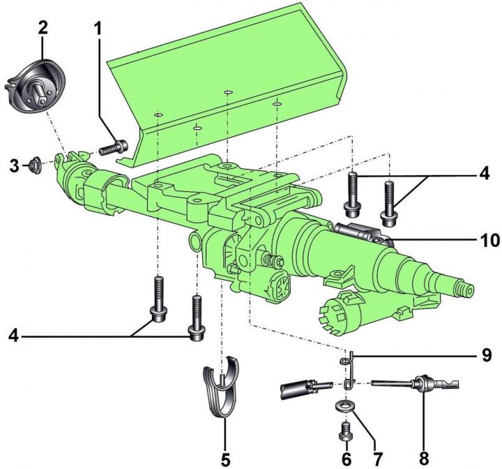
Fig. 14–3. Steering column: 1 – eccentric bolt; 2 – Power steering unit; 3 – self-locking nut, 30 Nm; 4 – combination bolts, 20 Nm; 5 – blocking lock; 6 – bolt, 7 Nm (for automatic transmission only); 7 – washer (for automatic transmission only); 8 – selector lever lock cable (for automatic transmission only); 9 – bracket (for automatic transmission only); 10 – steering column adjustment mechanism
When installing, it is necessary to use a new self-locking nut (Fig. 14–3).
Removal
The steering column must be replaced if the electric motor or the steering angle sensor (ESP) fails.
The steering column must be replaced only as an assembly, as its repair is not provided. Only the ignition switch can be replaced.
Before disconnecting the battery, find out if you have a radio activation code.
Turn off the ignition and disconnect the ground wire from the battery.
Set the wheels to move straight ahead.
Remove the steering wheel and steering column adjustment switch.
Using a screwdriver blade as a lever, remove the decorative trim from the steering column covers.
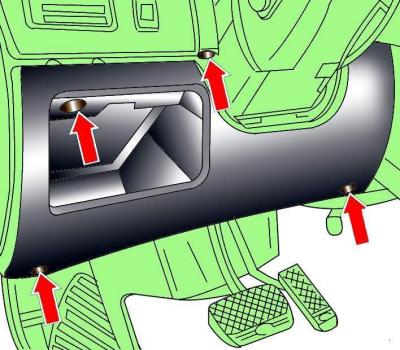
Fig. 14–4. Location of screws for fastening the decorative lower trim under the instrument panel on the driver's side
Remove the screws securing the decorative lower trim under the instrument panel on the driver's side (Fig. 14–4).
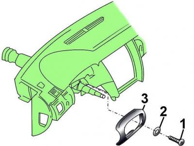
Fig. 14–5. Location of screw (1) with washer (2) for fastening the lower steering column cover (3)
Loosen the screws and remove the lower steering column cover (Fig. 14–5).
Disconnect the electrical connector or cable from the steering column position control unit located under the steering column.
On vehicles with an automatic transmission, disconnect the cable from the selector lever lock, turn the key in the ignition switch and remove the cable.
On vehicles with electric steering column adjustment, disconnect the electrical connectors from the steering column servomotors.
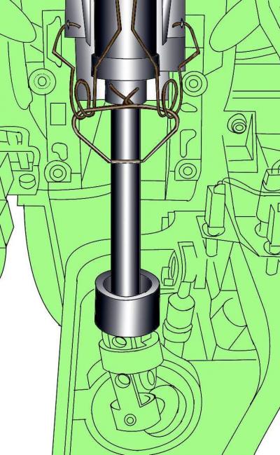
Fig. 14–6. Using a cord to rigidly connect the steering column elements together
Using a string passed through the hole in the base and the holes in the top of the steering column, firmly connect the column elements together (Fig. 14-6). This is necessary to prevent the base and the top of the steering column from separating when the column is removed.
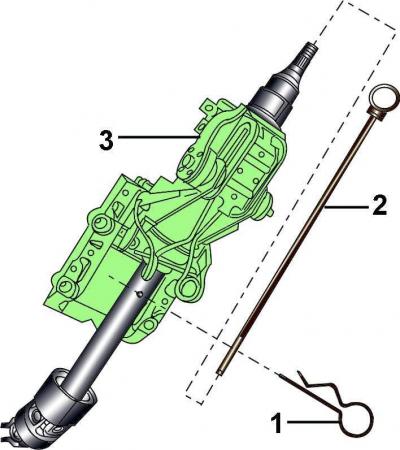
Fig. 14–7. Using the plastic rod (2) and the lock (1) to prevent the base and the upper part of the steering column from separating during transportation
To transport the steering column without damage, secure its base and upper part together using a plastic rod and a clamp (Fig. 14–7).
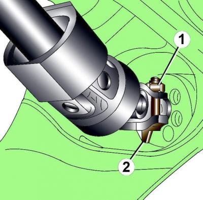
Fig. 14–8. Location of the nut (1) and clamp (2) for fastening the universal joint of the steering column
Unscrew nut 1 (Fig. 14–8) securing the universal joint of the steering column.
Loosen the eccentric bolt by turning it clockwise and remove it. Remove the steering column universal joint by moving it downwards.
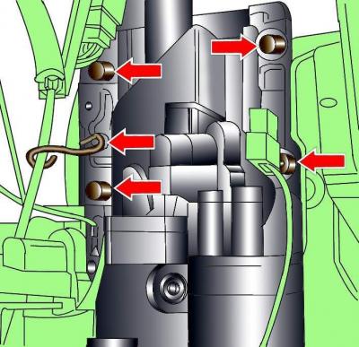
Fig. 14–9. Location of the steering column mounting bolts and steel bracket for mounting the selector lever lock cable
On vehicles with an automatic transmission, unscrew the steel bracket securing the selector lever lock cable, the steering column mounting bolts (Fig. 14–9) and remove the steering column.
Checking the technical condition
Check the steering column for damage and wear.
Check the smoothness and ease of rotation of the steering column shaft.
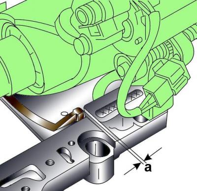
Fig. 14–10. Measurement location of the distance (a) between the movable element and the steering column bracket
Measure the distance a (Fig. 14–10) between the movable element and the steering column bracket. Distance a should be no more than 0.5 mm. If the distance a more than 0.5 mm, then the steering column is worn out and needs to be replaced.
Installation
The new steering column is supplied in a transport condition: the relative position of the base and the upper part of the steering column is fixed using a plastic rod and a retainer (see Fig. 14–7). After installing the steering column on the car, it is necessary to remove the retainer and the plastic rod.
Install the steering column on the vehicle and tighten the mounting bolts (see Fig. 14–9) so that the steering column can still move.
Install the universal joint onto the steering shaft, insert the eccentric bolt, turn it counterclockwise, install the nut onto the bolt and tighten it to 40 N·m (see Fig. 14–8).
If the steering column components were connected with a cord, remove it.
On vehicles with automatic transmission, connect the selector lever lock cable.
On vehicles with electric steering column adjustment, connect the electrical connectors to the steering column servomotors.
On vehicles with automatic transmission, install a steel bracket to secure the selector lever lock cable.
Install the casing and screw it on.
Install the decorative trim around the steering column covers.
Align the relative position of the steering column and tighten its mounting bolts to a torque of 20 N·m.
Install the lower trim panel under the driver's side instrument panel and secure it with screws.
Make sure the front wheels are set to move straight ahead.
Install the steering wheel.
Check that the distance between the steering column covers and the steering wheel is 3-4.5 mm.
Connect the ground wire to the battery.
Turn on radio and enter the code into it.
Raise the power windows all the way up. Then press all power window switches again for at least 1 second to the closed position to activate the power window control unit.
Set the time on the clock.