
1. Disconnect the negative battery cable.
2. Remove the trim panel covering the steering column.
3. Remove the steering wheel as described in Chapter 12.
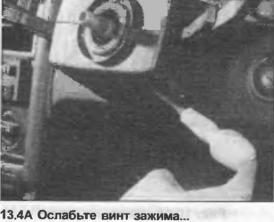
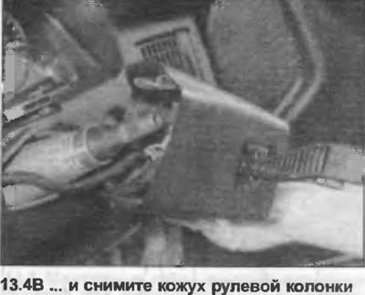
4. Remove the steering column shroud covers. On some models they are secured with several screws, while on other models they are secured with a clamp, and there is a hole to access the clamp screw (photo).
5. Disconnect the multi-pin plugs from the combination switch and ignition switch.
6. Remove the screw and take out the combination switch.
7. Remove the instrument panel, following the instructions Section 12.
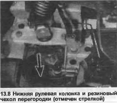
8. On direct acting steering models, remove the rubber boot from the bulkhead at the base of the column (photo).
9. On models with power steering, unscrew the column mounting flange from the pedal hanger.
10. Loosen and remove the clamp bolt, disconnect the flange pipe or coupling from the steering gear pinion.
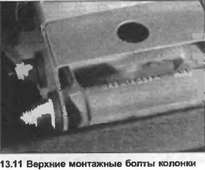
11. Using a socket wrench, unscrew the mounting bolts from the upper column (photo).
12. Release the column from the suspension, remove the threaded bracket.
13. Unscrew the lock casing from the column.
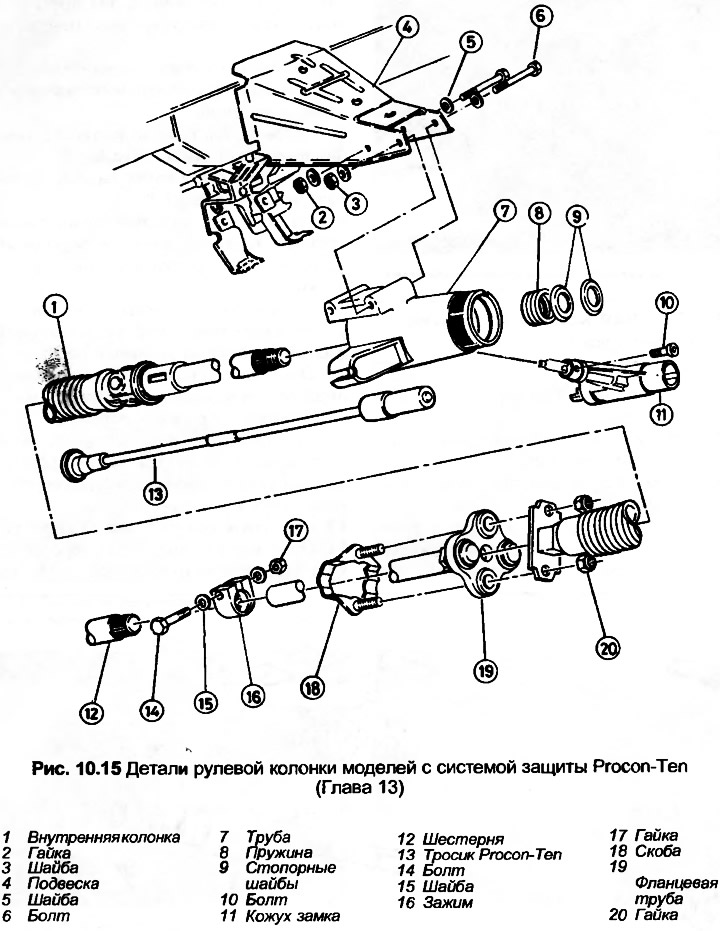
14. Lower the column through the bulkhead and remove it from under the panel. On models equipped with the Procon-Ten protection system, you will first need to disconnect the cable. Use caution with the Procon-Ten column tube as it consists of two halves joined together. On models from October 1988 onwards, the two halves are sealed with red paint which, if broken, indicates that the column is no longer serviceable due to accident damage. Do not expose the Procon-Ten column tube to temperatures exceeding 100°C, or clean it with solvents which may attack the coupling agent.
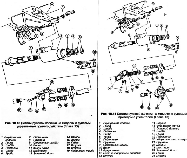
15. To disassemble the column, remove the upper spring washers and spring.
16. Remove the column from the pipe.
17. The bearing can be removed from the pipe using a suitable drift, except for models with the Procon-Ten system, where the bearing is one piece with the pipe.
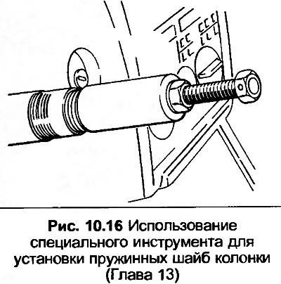
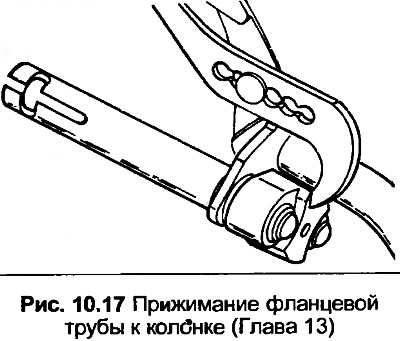
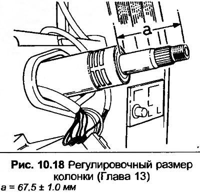
18. Assembly and installation is carried out in the reverse order of disassembly and removal. But note the following additional points. To install the spring washers on the top of the column, use the special tool shown in Fig. 10.16. On the standard version of the direct acting steering, press the flange pipe to the column with pliers as shown in Fig. 10.17, then adjust the position of the column until you get the size shown in Fig. 10.18. Fasten the column to the pinion. Before squeezing the clamp that secures the pipe to the bulkhead, make sure that the pipe is correctly connected to the inner column.
[This article was copied from the website: audimanual.ru]