
Table of contents: Removal ↓ Installation ↓
Removal
Lower the steering wheel all the way down.
Remove the ground cable from the battery.
Attention
- When disconnecting the wires from the battery terminals, the memory units of the control units erase the data on the recorded faults, so before disconnecting the wires, you must contact a workshop to recall the faults recorded in the memory. After connecting the wires to the battery terminals, it is necessary to activate and reprogram the electric windows, as well as the position of the rear-view mirrors and seats.
- If the car has a radio receiver with a code, then before disconnecting the wires from the terminals from the battery, check that there is a code to reactivate the receiver. Otherwise, the radio receiver can only be put into operation at a specialized station.
Remove the driver's side airbag.
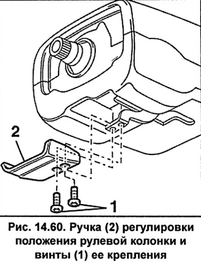
Unscrew two screws 1 (fig. 14.60) and remove the steering column position adjustment knob 2.
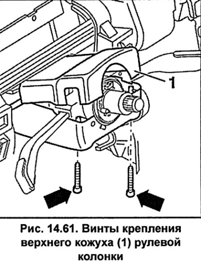
Remove the two screws and remove the upper steering column cover (see fig. 14.61).
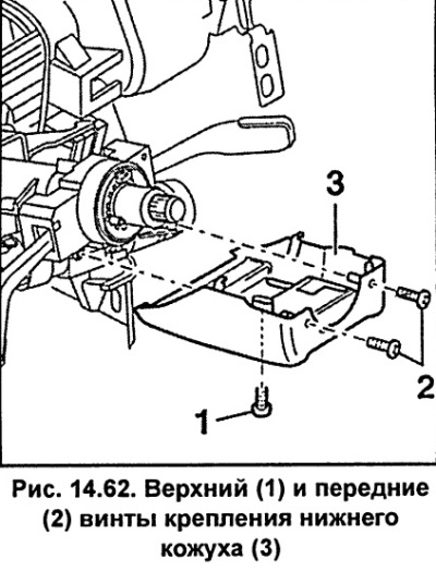
Unscrew the bottom 1 (fig. 14.62) and the two front 2 screws (3) securing the steering column and remove it.
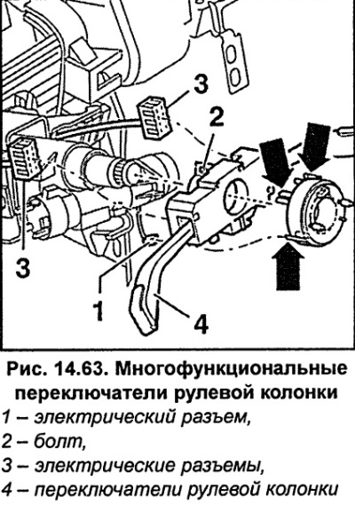
Disconnect electrical connector 1 (fig. 14.63).
The return ring with sliding ring can only be installed in the intermediate position. The front wheels must be set to move straight ahead.
Release the clamps (arrows, Fig. 14.63) and remove the return ring with the sliding ring from the steering column.
Check that the return ring remains in the intermediate position.
Unscrew bolt 2 (fig. 14.63) with a 5mm Allen head so that the steering column switches can be moved off the steering column.
Disconnect the electrical connectors from the steering column switches 3 (fig. 14.63).
Slide the switches 4 along the steering column (fig. 14.63) and take them off.
Installation
Install the switches onto the steering column, but do not screw them in yet.
Install the lower cover onto the steering column and secure with the front screws, tightening them to a torque of 0.6 Nm.
Screw in the bottom screw 1 (fig. 14.62) lower casing fasteners, but do not tighten them at this stage.
Install the return ring with the sliding ring.
Install the steering wheel.
Set the switches so that the gap between them and the steering wheel is 3 mm (see fig. 14.64).
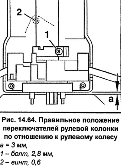
Tighten screw 1 (fig. 14.64) fastening of switches with a torque of 2.8 Nm.
Connect the electrical connectors to the switches.
Tighten bolt 2 (fig. 14.64) fastening the lower casing with a torque of 0.6 Nm.
Install the upper steering column cover and secure with screws, tightening them to a torque of 0.6 Nm.
Install handle 2 (fig. 14.60) adjust the steering column position and secure with screws, tightening them to a torque of 2.8 N·m.
Install the airbag.
Connect the ground wire to the battery.
Perform the operations to memorize the positions of seats, mirrors, etc., and also set the time on the clock and enter the code into the radio.
Install the steering wheel.
[The original article is available on the online resource: audimanual.ru]