
Table of contents: Removal ↓ Installation ↓
Removal
Before disconnecting the battery, find out if you have a radio activation code.
Turn off the ignition and disconnect the ground wire from the battery.
Set the wheels to move straight ahead.
Lower the steering wheel all the way down.
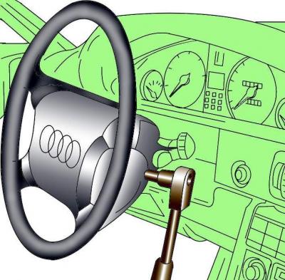
Fig. 18–50. Unscrewing the bolt securing the airbag to the steering wheel
Using a wrench, unscrew the Torx bolts securing the airbag, located on the sides at the rear of the steering wheel (Fig. 18–50).
Tilt the airbag back, disconnect the electrical connector and remove the airbag.
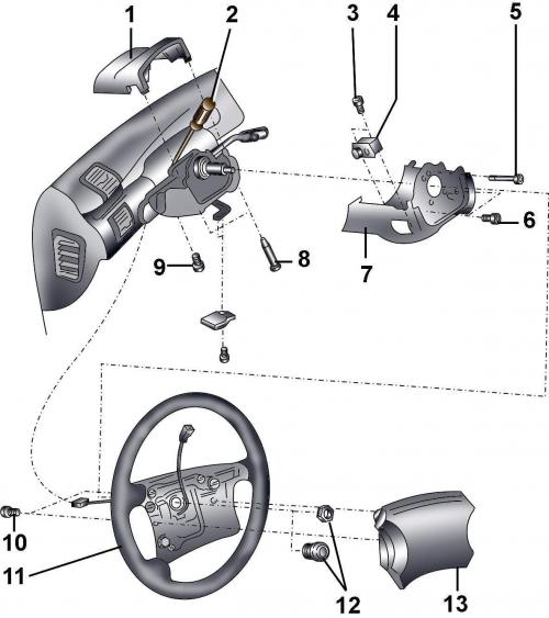
Fig. 18–51. Steering wheel, covers and steering column switches: 1 – upper casing; 2 – screwdriver (to unscrew the screw securing the steering column switches); 3, 5, 6 – screws, 0.6 Nm; 4 – steering column position adjustment switch (for vehicles with electric steering column adjustment); 7 – lower casing; 8 – screw, 0.6 Nm; 9 – bolt, 2.5 Nm; 10 – bolt; 11 – steering wheel; 12 – nut; 13 – airbag
Unscrew the two screws 8 (Fig. 18–51) and remove the upper casing 1 of the steering column.
Disconnect the electrical connector from the steering wheel coil, remove the nut (or bolt) and remove the steering wheel.
Pull the lower casing trim towards you and remove it.
Unscrew nut 12 and remove the steering wheel. When removing the steering wheel, the electrical connector of its spiral should not be disconnected.
On models with mechanical steering column adjustment, loosen the screw and remove the steering column adjustment knob.
Unscrew screws 5, 6 and bolt 9 and remove the lower casing 7 of the steering column.
On models with electric steering column adjustment, disconnect the electrical connector from the steering column adjustment switch. Loosen the screws 3 securing the switch 4 and remove it.
Using screwdriver 2, loosen the screw securing the steering column switches.
Disconnect the electrical connectors from the steering column switches.
Remove the switches from the steering column.
Installation
Install the switches on the steering column.
Temporarily install the steering wheel and secure it with the nut.
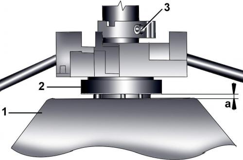
Fig. 18–52. Position of steering column switches when installed: 1 – steering wheel; 2 – steering column switches; 3 – screw; a = 3 mm
By moving switches 2 (Fig. 18–52) along the steering column, set them in such a position that the gap a between the switches and the steering wheel 1 is 3 mm, and in this position tighten the screw 3 of the switch fastening.
Further installation is carried out in the reverse order of removal.