
Table of contents: Removal ↓ Installation ↓
Removal
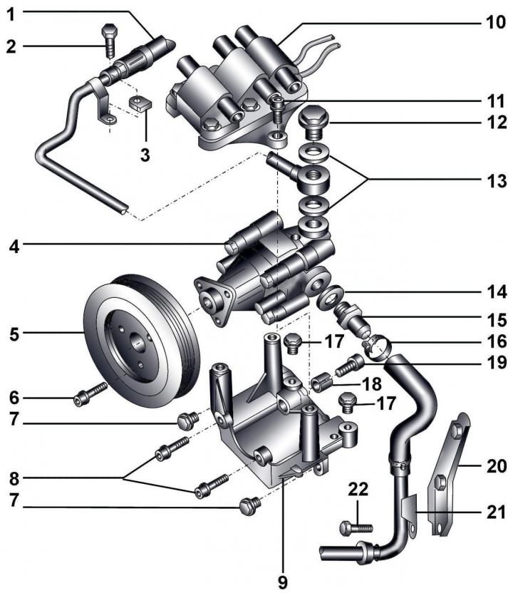
Fig. 14–25. Power steering pump for vehicles with 2.8 L petrol engines: 1 – hose with a pipe going to the steering mechanism; 2 – combination bolt, 8 Nm; 3 – mounting lug on the intake manifold; 4 – Power steering pump; 5 – pulley; 6, 7, 8 – bolts, 25 Nm; 9 – bracket; 10 – ignition coil with bracket; 11 – bolt, 25 Nm; 12 – hollow bolt, 50 Nm; 13, 14 – sealing rings; 15 – nipple, 50 Nm; 16 – clamp; 17 – bolt, 25 Nm; 18 – split bushing; 19 – bolt, 25 Nm; 20 – mounting bracket; 21 – Suction hose mounting bracket; 22 – combination bolt, 8 Nm
The power steering pump (see Fig. 14–25) is designed as a unit that cannot be repaired.
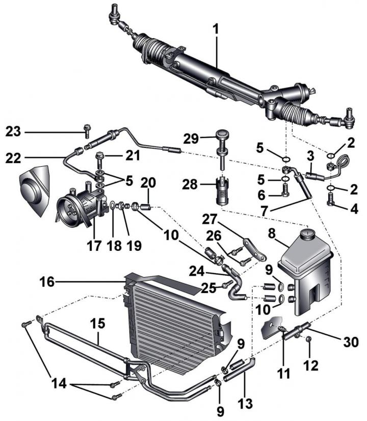
Fig. 14–22. Hydraulic power steering system for vehicles with 2.8 L petrol engines: 1 – steering mechanism; 2– sealing ring; 3 – pressure hose; 4 – hollow bolt, 40 Nm; 5 – sealing rings; 6 – hollow bolt, 50 Nm; 7 – return hose; 8 – reservoir; 9, 10 – clamps; 11 – rubber bushing; 12 – nut, 5 Nm; 13 – return hose from heat exchanger; 14 – combination bolts, 10 Nm; 15 – heat exchanger; 16 – radiator; 17 – Power steering pump; 18 – sealing ring; 19 – nipple, 50 Nm; 20 – suction hose; 21 – hollow bolt, 50 Nm; 22 – pipe, 40 Nm; 23 – combination bolt, 8 Nm; 24 – suction hose; 25 – combination bolts, 8 Nm; 26 – combination bolts, 10 Nm; 27 – bracket; 28 – mesh filter; 29 – cover with a dipstick for measuring the liquid level; 30 – clamp
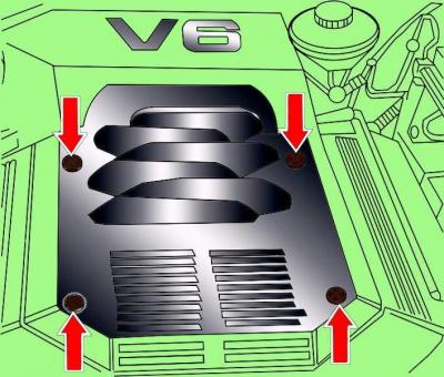
Fig. 14–23. Location of engine casing mounting screws
Remove the four screws and remove the engine cover (Fig. 14–23).
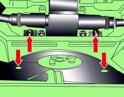
Fig. 14–24. Location of the screws for fastening the poly V-belt cover
Loosen the screws and remove the poly V-belt cover (Fig. 14–24).
With a hex key
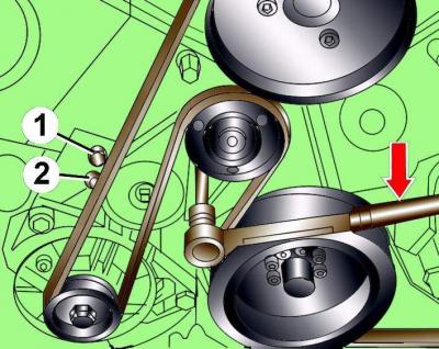
Fig. 14–26. Releasing the tension of the poly V-belt: 1 and 2 are the locations of the pins for fixing the tensioning mechanism. The arrow shows the direction of rotation of the Allen key to reduce the tension of the poly V-belt
10 mm loosen the tension of the poly V-belt by turning the tensioning mechanism clockwise until holes 1 and 2 are aligned (Fig. 14–26).
Fix the tensioning mechanism in this position by inserting a 5 mm diameter steel rod into the hole.
If necessary, unscrew and remove the poly V-belt pulley.
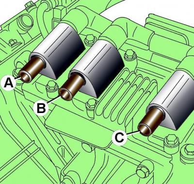
Fig. 14–27. High-voltage wire connections to ignition coils: A – ignition coil for cylinders 5 and 3; B – ignition coil 4 and 2 cylinders; C – ignition coil 6 and 1 cylinders
Disconnect the high-voltage wires from the ignition coils (Fig. 14–27).
Using clamp 3094, clamp the power steering hydraulic system suction hose.
Remove the hollow bolts and disconnect the suction and pressure hoses from the power steering pump.
Remove the bolts and remove the power steering pump together with the bracket.
Remove the bolts and remove the power steering pump from the bracket.
Installation
Installation is carried out in the reverse order of removal.
Before installing the pump, fill it with fresh G 002 000 fluid.
When installing, it is necessary to use new sealing rings and clamps.