
Table of contents: Models with 8-speed AT ↓ Models with 6-speed automatic… ↓
Models with 8-speed AT
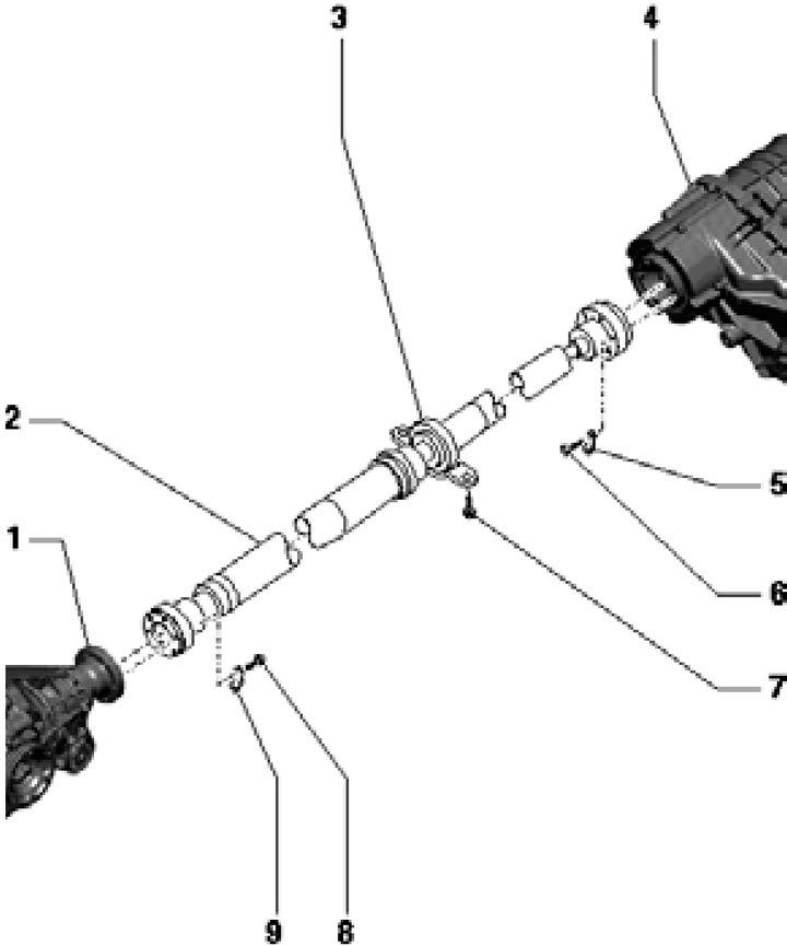
1. The installation details of the rear propeller shaft are shown in the illustration.
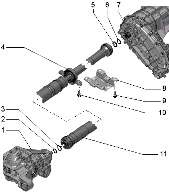
5.1. Rear propeller shaft installation details (models with 8-speed automatic transmission):
1 - Rear final drive;
2 - Sealing ring (black with a diameter of 25 mm or green with a diameter of 28 mm), subject to replacement;
3 - Retaining ring (black 25mm in diameter or silver 28mm in diameter), subject to replacement;
4 - Central bearing of the propeller shaft;
5 - Retaining ring (black silver diameter 28 mm), subject to replacement;
6 - Sealing ring (green, 28 mm in diameter), subject to replacement;
7 - Transfer case;
8 - Central tunnel support;
9 - Bolts, 6 pcs., 60 Nm;
10 - Bolts, 2 pcs., 20 Nm;
11 - Rear propeller shaft.
2. On both sides, loosen the clamp and slightly lower the exhaust pipe tips. Lower the rear of the exhaust system and support it as shown in the illustration.
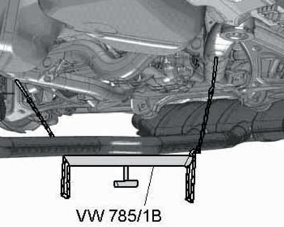
5.2. Holding the exhaust pipe down.
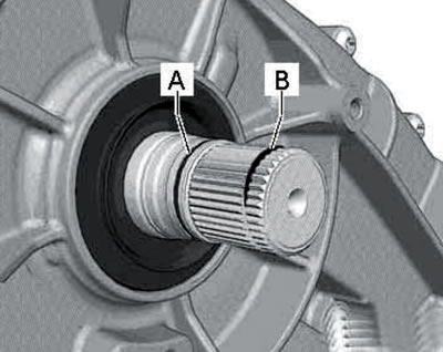
3. With a suitable lever (1 in the illustration) press the rear propeller shaft out of the transfer case.
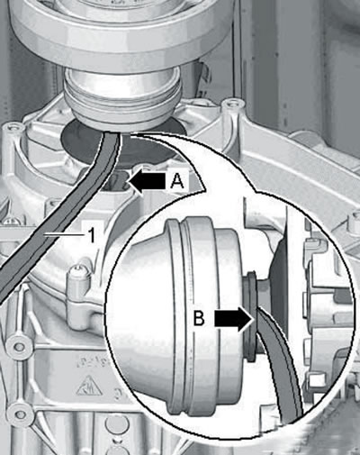
5.3. Separating the cardan shaft from the transfer case.
In this case, rest the lever on the surface (A) and the bushing (B), and not on the boot, since if the boot is damaged, the driveshaft will have to be replaced.
4. Follow the steps described in paragraphs 11-12 of Section 4.
5. Remove the bolts (2-7 in the illustration) and remove the central tunnel support.
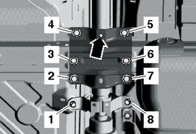
5.5. Rear propeller shaft central mount.
Remove the bolts (1 and 8) of the central bearing bracket and remove the rear propeller shaft. Place it with the center bearing bracket facing up.
6. Before installation, replace the sealing ring (1 in illustration 4.15) and a retaining ring (2) on the end of the main transmission shaft, as well as a sealing ring (And in the illustration) and the retaining ring (B) on the transfer case.
5.6. Sealing (A) and retaining ring (B).
7. First, hand tighten the center bearing bracket bolts. Then insert the propeller shaft into the rear final drive and only then tighten the bolts (2-7 in Illustration 5.5) supports of the central tunnel. The round hole (arrow) should be at the front. After this, finally tighten the center bearing bracket bolts.
8. Further installation is carried out in reverse order.
Models with 6-speed automatic transmission
9. The details of the rear propeller shaft installation are shown in the illustration.
5.9. Rear propeller shaft installation details (models with 6-speed automatic transmission):
1 - Rear final drive;
2 - Rear propeller shaft;
3 - Central bearing of shaft 2;
4 - Transfer case;
5, 9 - Locking plate;
6, 8 - Bolts, subject to replacement, 30 Nm, then tighten to an angle of 90°;
7 - Bolts, 20 Nm.
10. Set the selector lever to the "N" position.
11. Make sure that the factory color marks are present on the rear propeller shaft and on the rear final drive flange (see illustration 4.3). If these marks are not visible, apply them.
12. Remove the bolts (see illustration) fastening the rear propeller shaft to the rear final drive, leaving one bolt screwed in by hand. Hold the shaft from turning using the T10172 tool with T10172/6 adapters.
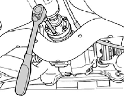
5.12. Bolts for fastening the rear propeller shaft to the rear final drive.
13. Remove the bolts (1 in illustration 2.5) fastening the rear propeller shaft to the transfer case, holding the shaft from turning using the T10172 device with T10172/6 adapters. Tie the rear propeller shaft to the body.
14. Remove the bolts (2-7 in Illustration 5.5) and remove the central tunnel support. Remove the bolts (1 and 8) of the central bearing bracket and remove the rear propeller shaft. Place it with the center bearing bracket facing up.
15. Installation is carried out in reverse order. Use new driveshaft mounting bolts. Make sure the marks are aligned.
(This publication is borrowed from the resource «AudiManual»)