



Table of contents: Pressing out the flange with the… ↓ Pressing in the sealing flange with… ↓ Assembly ↓ Crankshaft ↓
The gearbox is removed. For better understanding, the procedure is shown with the engine removed.
Pressing out the flange with the sensor wheel from the crankshaft
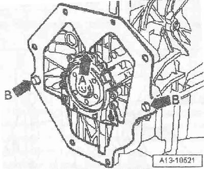
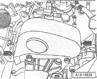
Remove the flywheel. Press the intermediate shield off the centering bushings "arrow B" and disconnect it from the flange "arrow A" from above. Remove the upper toothed belt cover, for this purpose open the clamping clamps "arrows".
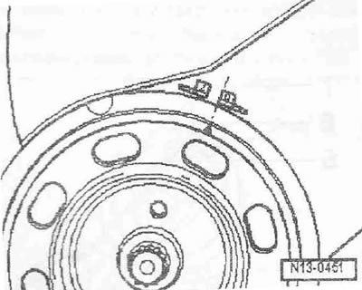
Set the crankshaft in the direction of engine rotation to "TDC". The mark on the poly V-belt pulley for the crankshaft should coincide with the edge of the "0" mark.
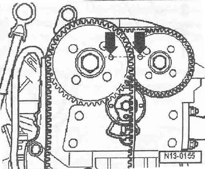
The fixing holes in the camshaft sprockets must match the gauge holes in the camshaft housing "arrows". If the fixing holes are on opposite sides, the crankshaft must be turned one more revolution.
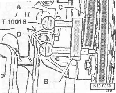
Fix the camshafts using the camshaft locking tool "T10016": the locking pin must be inserted through the locking hole of the intake camshaft pulley "C" into the calibration hole on the camshaft bearing housing. The second locking pin must be inserted through the locking hole of the exhaust camshaft gear into the calibration hole on the camshaft bearing housing. The handles of the locking pins must be at the same height "line A". Remove the oil pan.
Unscrew the bolt "arrow" and remove the engine speed sensor "G28".
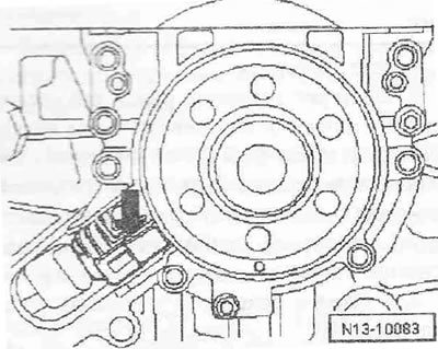
Unscrew the sealing flange bolts.
Instructions: The sealing flange is pressed out of the crankshaft together with the toothed ring.
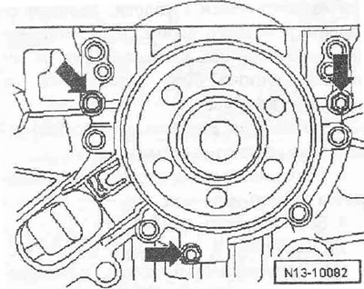
To press out, screw 3 bolts "arrows" into the sealing flange alternately by max. 1/2 turn. Remove the sealing flange with the toothed rim.
Pressing in the sealing flange with the sensor wheel
Instructions. The sealing flange with a Teflon sealing cuff is equipped with a support ring for the working edges. This support ring serves as a mounting sleeve and must not be removed before installation. After removing the flange from the packaging, it is prohibited to separate or rotate the sensor wheel. The toothed ring is installed in the installation position by fixing it on the pin of the "T10017" mounting device. The sealing flange and cuff are one element, so they can only be replaced together with the sensor wheel. The "T10G17" mounting device is brought to the installation position relative to the crankshaft by means of a guide pin, which is inserted into the crankshaft hole.
Construction of the mounting device "T10017"
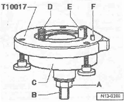
A. Nut
B. Clamping surface
C. Mounting cap
D. Hexagon socket head bolt
E. Guide bolt
F. Locking pin
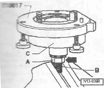
A. Installing the flange with the toothed rim on the mounting device "T10017". Screw the nut "A" almost to the clamping surface "B" of the threaded pin. Clamp it in the mounting device "T10017" in the area of the clamping surface of the threaded pin. Press the casing "C" down so that the "arrow" stands on the nut. The inner part of the device and the mounting pin must be at the same distance.
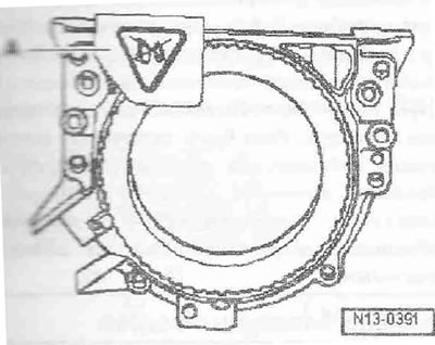
Remove retaining clip "A" from the new sealing flange.
Instructions: Do not turn the toothed pin or remove it from the flange.
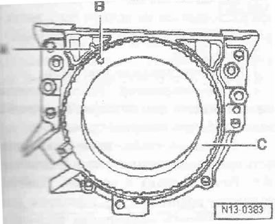
The fixing hole "B" in the toothed "C" must coincide with the mark "A" on the flange.
Place the flange with the front side on a flat surface. Press the retaining ring of the working edges "A" down so that it lies on the flat surface "arrow".
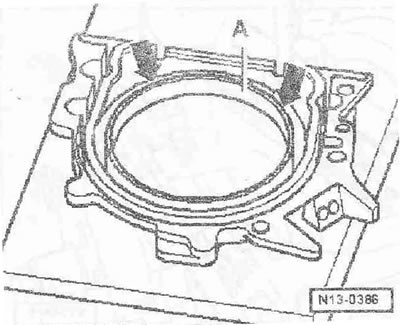
The upper edge of the support ring of the working edges and the front edge of the sealing flange must be at the same level of the "arrow".
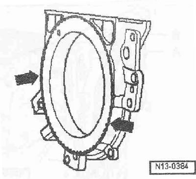
Place the sealing flange with the front side on the mounting device T10017 so that the locking pin "A" enters the hole "B" of the toothed ring. The flange must lie flat on the mounting device.
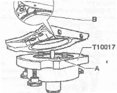
Press the flange and the support ring of the working edges "B" while tightening the 3 knurled bolts "A" to the surface of the mounting device "T10017" so that the locking pin cannot slip out of the hole in the ring gear.
Instructions: When installing the flange, make sure that the sensor wheel remains fixed in the mounting device.
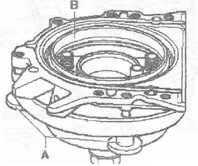
B. Installation of the mounting device "T10017" with a sealing flange on the crankshaft flange.
There should be no oil or grease on the crankshaft flange. The engine is set to "TDC". Screw nut "A" to the end of the threaded pin. Press the threaded pin of the mounting device "T10017" in the "direction of the arrow" until nut "A" is pressed against the casing "C".
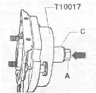
Align the cut side of the casing with the sealing surface of the cylinder block on the oil pan side. Fasten the "T10017" device to the crankshaft flange by screwing the Allen bolts "A" into the crankshaft flange by approximately 5 thread turns.
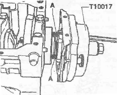
Screw 2 bolts M6x35 "pos. A" in the direction of the flange into the cylinder block.
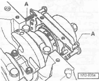
C. Fastening the mounting device "T10017" to the crankshaft flange
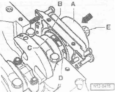
Manually move the casing "A" in the direction of the crankshaft flange "C" "arrow" until the support ring of the working edges "B" rests on the flange. Push the guide pin "D" into the crankshaft hole, as a result of which the toothed ring takes its final installation position. Tighten both Allen bolts of the mounting device. Screw the nut "E" by hand onto the threaded pin until it is pressed against the casing "A".
D. pressing the toothed ring onto the crankshaft flange using the mounting device "T10017"
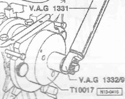
Tighten the nut of the mounting device "T10017" with a torque of 35 Nm. After tightening the nut with a torque of 35 Nm, there should still be a small gap between the cylinder block and the sealing flange.
E. Checking the mounting position of the ring gear on the crankshaft.
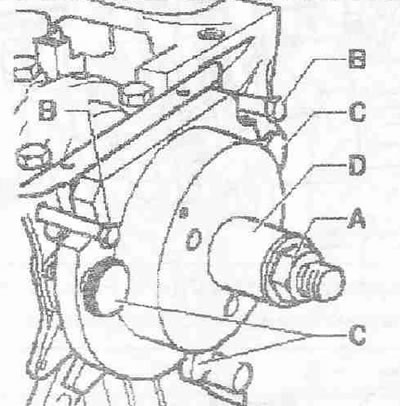
Screw nut "A" to the end of the threaded pin. Unscrew both bolts Mbx35 "pos. B" from the cylinder block. Unscrew 3 knurled bolts "C" from the sealing flange. Remove device "T10017" and the support ring of the working edges.
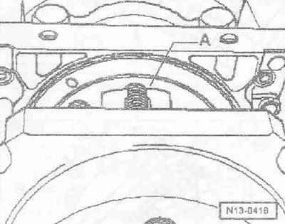
Install the depth gauge on the crankshaft flange "A".
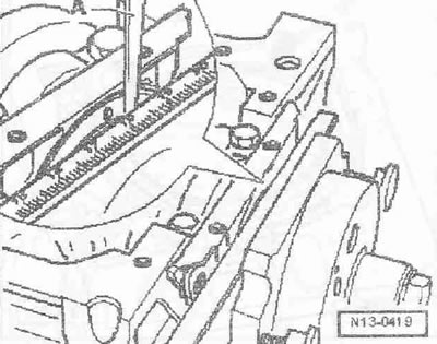
To measure between the depth gauge and the gear ring, use the plate feeler gauge "A".
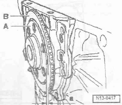
Measure the distance "a" between the crankshaft flange "A" and the toothed crown "B". Specified value: Distance "a" = 0.5 mm. If the nominal value is too small, then press the toothed crown further. If the specified value is reached, carry out further installation.
F. Additional pressing of the gear ring.
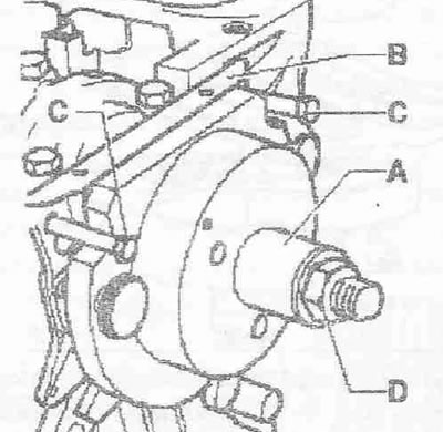
Move the casing "A" by hand towards the sealing flange "B". Screw in 2 bolts M6x36 "pos. C" to guide the sealing flange "B" into the cylinder block. Screw the nut "D" by hand onto the threaded pin until it rests on the casing.
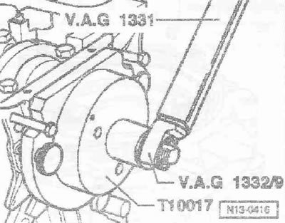
Tighten the nut of the mounting device "T10017" with a torque of 40 Nm. Check the installation position of the toothed ring on the crankshaft again. If the nominal value is too low, tighten the nut of the mounting device "T10017" with a torque of 45 Nm. Check the installation position of the toothed ring on the crankshaft again.
Assembly
Replace flange bolts. Install engine speed sensor "G28". Install oil pan.
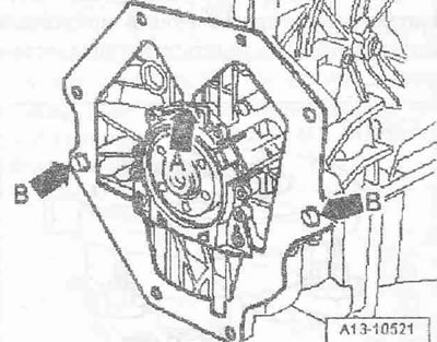
Connect the upper intermediate shield to the flange "arrow A" and place it on the centering bushings "arrow B". Install the flywheel.
Crankshaft
Caution! Do not remove the crankshaft. Unscrewing the main bearing cap bolts causes deformation of the cylinder block main bearing beds. Such deformations reduce the bearing clearance. Even if the bearing shells are not replaced, the bearings may be damaged due to the changed clearance. If the bearing cap bolts have been unscrewed, the cylinder block must be replaced entirely together with the crankshaft. Measuring the clearance in the main bearings in a service station is impossible.