
Withdrawal
If available, unscrew the four bolts and remove the transverse beam located under the pipes of the exhaust system.
Unscrew the nuts securing the exhaust pipe connecting clips, disconnect and remove the rear section of the exhaust system.
Unscrew the bolts and remove the heat shield located above the cardan shaft.
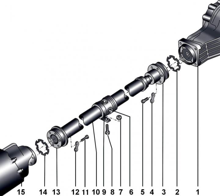
Pic. 11–1. Cardan shaft and main reverse gear: 1 - main reverse gear; 2 - gasket; 3 - hinge of equal angular velocities; 4 - fixing plate; 5 - self-locking bolt, 55 Nm; 6 - universal joint; 7 - adjusting gasket; 8 - bolt, 23 Nm; 9 - intermediate support of the cardan shaft; 10 - cardan shaft; 11 - self-locking bolt, 55 Nm; 12 - fixing plate; 13 - hinge of equal angular velocities; 14 - gasket; 15 - gearbox
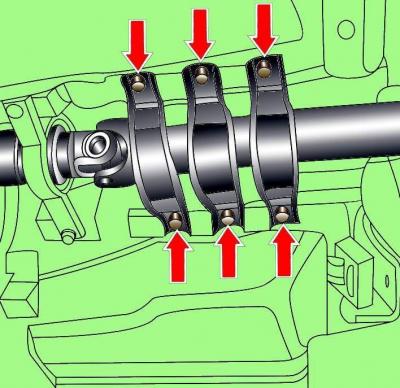
Pic. 11–2. Arrangement of bolts of fastening of the propeller shaft tunnel
Unscrew the bolts and remove the tunnel (pic. 11–2).
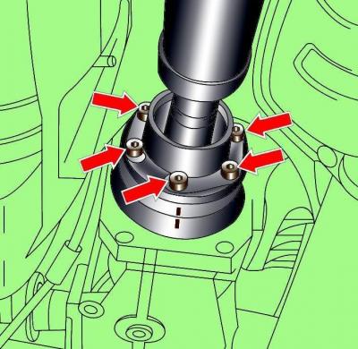
Pic. 11–3. Location of alignment marks and bolts for fastening the propeller shaft to the flange of the main reverse gear
Check for alignment marks on propeller shaft and final drive flange (pic. 11–3). If there are no marks, apply them.
Loosen the bolts securing the propeller shaft flanges to the gearbox and final reverse gear flanges (see fig. 11–3).
Loosen the propshaft intermediate support bolts.
Install and secure tool 3139 to the driveshaft to keep the driveshaft from bending.
Completely unscrew the bolts securing the propeller shaft flanges to the gearbox and final reverse gear flanges, as well as the propeller shaft intermediate support.
Move the cardan shaft hinges along the splines of the shaft and remove the cardan shaft from the vehicle.
Remove tool 3119 from propeller shaft.
Installation
Installation is carried out in the reverse order of removal, taking into account the following.
In the flanges of the gearbox and final reverse gear, clean the threads for the crankshaft mounting bolts.
Check that there is no grease on the propshaft flanges. Remove the protective film from the new gaskets and install the gaskets on the flanges with the sticky side to the cardan shaft.
To eliminate imbalance, align the marks on the driveshaft flange with the marks on the flanges of the gearbox and final reverse gear (see fig. 11–3).
Note: The maximum deflection angle of the axis of the constant velocity joint is 8°, the universal joint is 25°.
Fasten the propeller shaft with new bolts.
Adjust the position of the propeller shaft intermediate support.
Check that the exhaust system is located freely and does not touch the body.
Visitor comments