
Table of contents: Removal ↓ Installation ↓
Removal
Using a screwdriver blade as a lever, remove the cap from the center of the wheel rim.
With the vehicle standing on its wheels, loosen the bolts securing the outer CV joints to the rear wheel hubs.
Raise the rear of the car and secure it on stands. Remove the rear wheels.
Remove the bolt and ABS sensor from the steering knuckle.
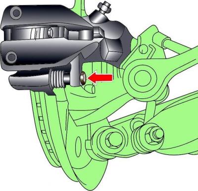
Fig. 11–9. Bolt location (the second one is not visible) rear brake caliper mounts
Unscrew the bolts, remove the rear brake caliper and tie the caliper to the body with soft wire (Fig. 11-9). The caliper should not hang on the brake hose.
Remove the brake disc.
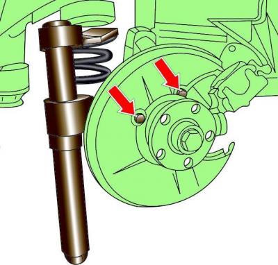
Fig. 11–10. Bolt locations (the third bolt is not visible) fastenings of the protective cover of the brake disc and a special device for compressing the front suspension spring
Unscrew the bolts and remove the brake disc protective cover (Fig. 11–10).
Using a special tool, compress the front suspension spring and remove it (see Fig. 11–10). When using a special tool to compress springs, firmly grasp the spring coils and compress the spring from opposite sides.
Warning: The spring has a very high compression force, so use only a very reliable tool. Do not tie the spring with wire under any circumstances.
Unscrew the inner CV joint from the final drive flange.
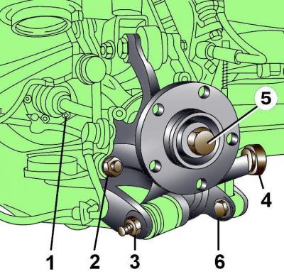
Fig. 11–11. Fastening elements of the drive shaft and steering knuckle: 1 – bolt for fastening the drive shaft to the main rear gear drive flange; 2 – earring fastening nut; 3 – lower arm mounting nut, 80 Nm + turn further by 90°; 4 – control rod (before 1996 – 95 Nm, since 1997 – 70 Nm + turn by 90°); 5 – bolt for fastening the drive shaft to the hub; 6 – lower arm mounting bolt, 80 Nm + turn further by 90°
Unscrew the fastening nut 2 (Fig. 11–11) of the stabilizer earring and remove the earring from the steering knuckle.
Unscrew bolts 6 and nut 3 of the lower mount of the steering knuckle.
Unscrew the nut and, using a puller, remove the steering rod 4 from the steering knuckle.
Unscrew the bolt 5 securing the outer CV joint to the rear wheel hub.
Tilt the lower part of the steering knuckle to the side and remove the drive shaft.
Under no circumstances should the vehicle be lowered onto its wheels with one or two drive shafts removed, as this will damage the wheel hub bearings. If it is necessary to place the vehicle on its wheels and move it with the drive shafts removed, install the outer CV joint instead of the shaft and tighten its mounting bolt to a torque of 50 Nm.
Installation
Installation is carried out in the reverse order of removal, taking into account the following.
When installing, it is necessary to use new self-locking nuts and a bolt for fastening the outer CV joint to the hub.
Attach the drive shaft to the final drive flange and tighten the bolts to 77 N·m.
Install on steering knuckle ABS sensor.
Install and tighten the nuts and bolt securing the lower arm and control rod (see Fig. 11–11).
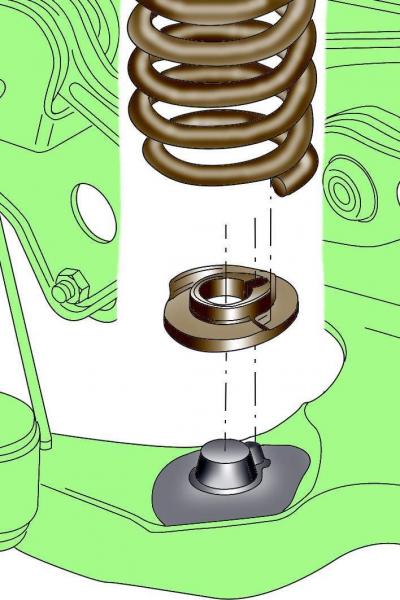
Fig. 11–12. Correct positioning of the lower spring coil in the spring plate
Install the rear suspension spring in place and remove the device from it so that its lower end is correctly positioned in the lower spring plate (Fig. 11-12).
Install the rear brake caliper.
Apply a thin layer of grease to the flange of the hub that centers the wheel disk. Install the wheel and secure it with bolts. Lower the car and tighten the wheel mounting bolts to the required torque.
Screw in and tighten the bolts securing the outer CV joints to the front wheel hubs to a torque of 190 Nm and additionally tighten them by an angle of 180°. Tighten the bolts securing the drive shafts to the front wheel hubs only when the vehicle is standing on its wheels.
The original version is on the portal: AUDImanual