
Table of contents: Removal ↓ Installation ↓
Removal
Using a screwdriver blade as a lever, remove the cap from the center of the wheel rim.
With the vehicle standing on its wheels, loosen the bolts securing the drive shafts to the front wheel hubs.
Raise the front of the car and secure it on stands. Remove the front wheels.
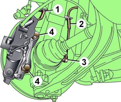
Fig. 12–11. Location of ABS sensor (3), clamps for fastening wires of ABS sensors (2) and brake pad wear (1), caliper mounting bolts (4)
Release the brake pad wear sensor wire from clamp 1 (Fig. 12–11)
Remove ABS sensor 3 from the steering knuckle and disconnect 2 sensor wires from the clamp.
Unscrew bolts 4, remove the front brake caliper and tie the caliper to the body with soft wire. The caliper should not hang on the brake hose.
Remove the brake disc.

Fig. 12–4. Upper mount elements of the steering knuckle: 1 – nut and bolt for mounting the ball joints of the upper arms of the front suspension; 2 – ball joints of the upper arms of the front suspension; 3 – steering rod end mounting bolt; 4 – square head bolt
Unscrew the bolts securing the tie rod end to the steering knuckle (see Fig. 12–4).
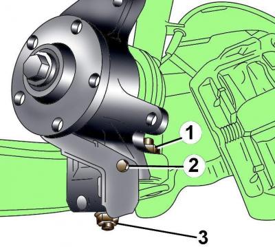
Fig. 12–12. Location of nuts (1 and 3) securing the ball joints of the lower arms of the front suspension and bolt (2) securing the protective cover
Unscrew the bolts and remove the brake disc protective cover (Fig. 12–12).
Using a ball joint puller, remove the lower retaining and control arm ball joints from the steering knuckle, being careful not to damage the drive shaft constant velocity joint boot.
Remove the flange bolt securing the drive shaft.
Unscrew the nut, remove the bolt securing the ball joints of the upper control arms of the front suspension to the steering knuckle (see Fig. 12-4) and remove the ball joints from the steering knuckle. Do not widen the grooves in the steering knuckle when removing the upper control arms.
With the steering knuckle tilted away from the vehicle, remove the drive shaft from the front wheel hub and the lower control arm ball joint from the steering knuckle.
Remove the steering knuckle from the vehicle.
Installation
Installation is carried out in the reverse order of removal, taking into account the following.
Screw in and tighten the bolts securing the outer CV joints to the front wheel hubs to a torque of 190 Nm, then turn them an additional 180°. Tighten the bolts securing the drive shafts to the front wheel hubs only when the vehicle is standing on its wheels.
Adjust front wheel alignment angles.