
Table of contents: Removal ↓ Installation ↓
Removal
Loosen the front wheel mounting bolts, then raise the front of the car and secure it on stands. Remove the front wheel.
Using a screwdriver blade as a lever, remove the rubber plugs located on the top of the front suspension.
Unscrew the nuts of the upper shock absorber mount through the opened holes.
Unscrew the bolt securing the ball joints of the upper arms of the front suspension to the steering knuckle.
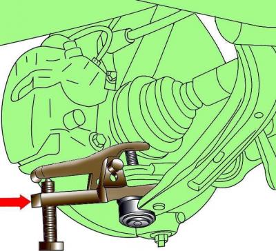
Fig. 12–1 Using a puller to remove the lower control arm ball joint from the steering knuckle
Unscrew the nut securing the ball joint of the lower retaining arm to the steering knuckle. Using a puller, remove the ball joint from the steering knuckle (Fig. 12-1).
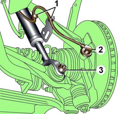
Fig. 12–2. Location of ABS sensor (2), wire mounting clamps (1) for ABS and brake pad wear sensors, lower shock absorber strut mounting bolt (3)
Remove the ABS sensor from the steering knuckle and disconnect the sensor wires from the clamps (Fig. 12–2).
Disconnect the brake pad wear sensor wires from the clamps.
Unscrew the lower shock absorber strut mounting bolt, being careful not to damage the protective cover of the constant velocity joint of the drive shaft.
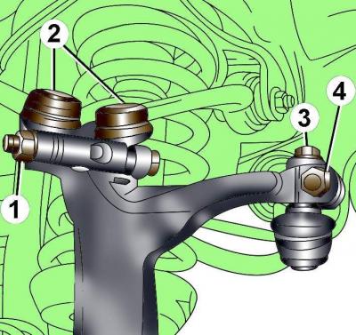
Fig. 12–4. Upper mount elements of the steering knuckle: 1 – nut and bolt for mounting the ball joints of the upper arms of the front suspension; 2 – ball joints of the upper arms of the front suspension; 3 – steering rod end mounting bolt; 4 – square head bolt
Unscrew the nut and remove the bolt securing the ball joints of the upper front suspension arms to the steering knuckle (Fig. 12-4) and remove the ball joints from the steering knuckle. Do not widen the grooves in the steering knuckle when removing the upper transverse arms.
Do not remove the tie rod end mounting bolt or square head bolt, as this will disturb the front wheel alignment angles.
Tilt the top of the steering knuckle to the side.
Carefully remove the shock absorber strut from under the front fender, being careful not to damage the protective boot of the constant velocity joint of the drive shaft.
Installation
When installing, it is necessary to use new bolts, nuts, washers, and clamping sleeve (before installing it, apply grease G 000 650 to the hole in the steering knuckle), clamp.
Installation is carried out in the reverse order of removal, taking into account the following.
Install the shock absorber strut so that the hole in the spring seat is located on the side of the front longitudinal element.
Install the lower shock absorber mount fork onto the control arm and secure with the bolt and nut.
Install the upper wishbones until they stop against the steering knuckle and secure them with the bolt and nut, tightening to a torque of 40 N·m (see Fig. 12–4).
Secure the ABS sensor wire to the brake caliper bracket.
Secure the upper part of the shock absorber strut with nuts, tightening them to a torque of 20 Nm.
Install the rubber plugs.
Apply a thin layer of grease to the flange of the hub that centers the wheel disc. Install the wheel and secure it with bolts. Lower the car and tighten the wheel mounting bolts to a torque of 120 N·m.