
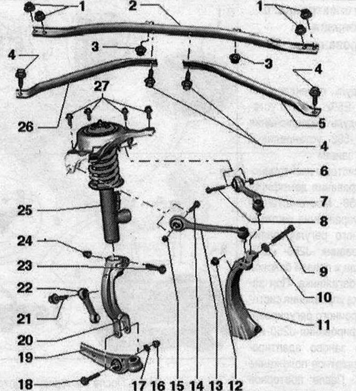
I 1. Nut. 20 Nm; 2. Stretching; 3. Nut. 2 Nm.; 4. Bolt. 20 Nm; 5. Additional element hardness on the left; 6. Nut. 50 Nm + turn 90°. Replace each time removed. Tighten only in the vehicle position without load. When tightening, apply pressure on the suspension arms towards the inside of the vehicle; 7. Suspension arm at the top rear; 8/ 9. Bolt. Replace each time when removed; 10. Washer; 11. Wheel bearing housing; 12. Nut. 40 Nm. Replace each time when removed; 13. Upper front suspension arm; 14. Bolt. Replace each time when removed; 15. Nut. 50 Nm + turn 90°. Replace each time removed. Tighten only in the vehicle position without load. When tightening, apply pressure on the suspension arms towards the inside of the vehicle; 16. Nut. 90 Nm + turn 90°. Replace each time removed. Tighten only in the vehicle position without load; 17. Washer; 18. Bolt. Replace each time when removed; 19. Support arm; 20. Shock absorber fork; 21. Bolt. 40 Nm + turn 90°. Replace each time removed. Tighten only in the vehicle position without load; 22. Connecting rod. Consider the installation position, take into account the different versions: aluminum and steel, suitability. Simultaneous installation of 2 racks of different types is unacceptable; 23. Bolt. 40 Nm + tighten by +180°. Replace each time when removed; 24. Nut. Replace each time when removed; 25. Shock absorber strut. It is necessary to take into account the differences in the design of the chassis, see the vehicle data plate. Faulty shock absorbers must be emptied and degassed before disposal; 26. Additional element rigidity on the right; 27. Bolt. 40 Nm + turn 90°. Observe tightening sequence. Replace every time removed
Visitor comments