
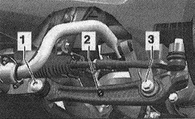
Disconnect bolt connections "1" and "3". Remove connecting rod "2".
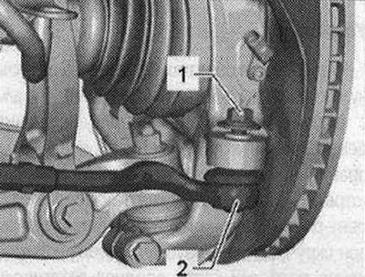
Loosen nut "1" of tie rod end pin "2" until it is flush with the pin thread. If necessary, hold it from turning while loosening.
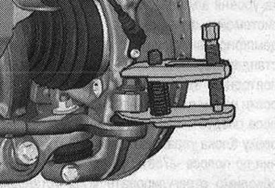
To protect the thread, leave the nut on the pin screwed on for several turns. Press out the end of the transverse steering rod from the hub bearing housing using the ball joint puller "T40010 A". Then unscrew the nut.
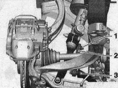
Disconnect bolted connection "3". Disconnect threaded connection "1", remove the support arm and tilt it forward.
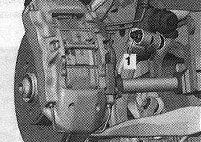
To remove bolt "1", depending on the side of the car, turn the steering gear all the way to the left or right. Disconnect bolt connection "1".
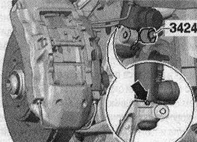
Insert the rectifier "3424" into the slot of the wheel bearing housing. Turn the ratchet 90° and remove it from the rectifier "3424". Pull the shock absorber fork downwards and remove it from the shock absorber tube.
Installation
Installation is carried out in the reverse order. In this case, it is necessary to observe the tightening torques. On vehicles with electronic damping control, ensure that the T-pin "arrow" is correctly secured in the groove of the shock absorber fork during installation. The "belt" blocks have a limited working torsion range. Therefore, the bolted connections of the wheel suspension should only be tightened when the vehicle is in the unloaded position or in the standard suspension position. Raise the wheel support with the suspension in the static position on vehicles with coil springs. On vehicles with automatic transmission and headlight range control, perform the basic setting of the headlights. After removing and installing the vehicle level sensor or loosening the rods on vehicles with electronic damping control, the standard suspension position must be readjusted. After repeated adaptation of the adjustment position on vehicles with lane assist, the lane assist control unit "J759" must be recalibrated. Tighten the wheel. The wheel alignment angles must be adjusted.