
Suspension strut and wheel bearing housing
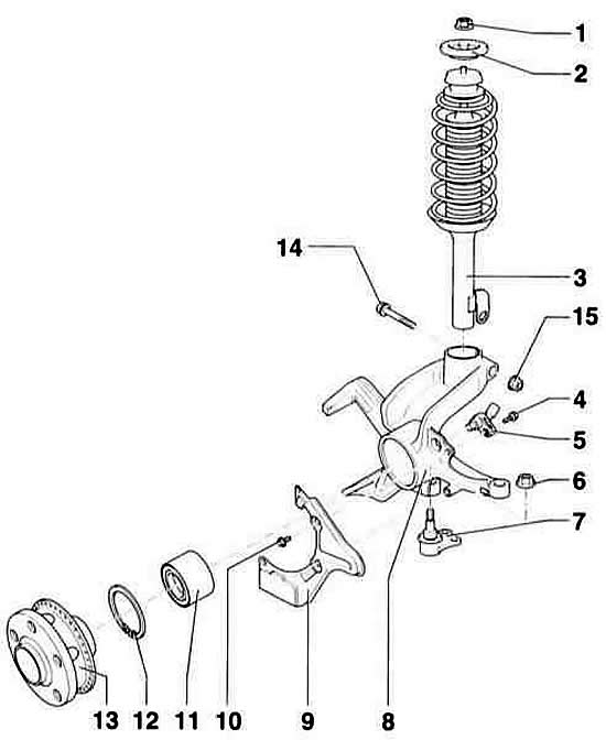
- 1 - collar nut, 60 Nm. Self-locking, must be replaced.
- 2 - cup
- 3 - shock absorber. To replace the spring or shock absorber, it is removed and installed as a complete set.
- 4 - hexagon socket screw, 8 Nm
- 5 - ABS sensor
- 6 - nut, 45 Nm. Self-locking, must be replaced.
- 7 - ball joint
- 8 - wheel bearing housing
- 9 - cover
- 10 - bolt, 7 Nm
- 11 - wheel bearing
- 12 - retaining ring
Take out together with regular tongs. Be sure to install in the correct position.
- 13 - hub. With rotor for ABS sensor
- 14 - bolt. Be sure to replace.
- 15 - nut, 50 Nm + 90° (1/4 turn). Self-locking, must be replaced.
Withdrawal
1. Remove the wheel cover. On light alloy wheels, the cap is removed using removable hooks from the on-board tool kit.
2. Loosen the hex nut securing the drive shaft to the hub.
Warning: When removing the bolt, the vehicle must be on its wheels. There is a danger of an accident due to the large opening torque!
3. Mark with paint the position of the corresponding front wheel relative to the hub. This will allow the assembly to install the balanced wheel in its original position. Loosen the wheel bolts with the vehicle on the ground. Raise the front of the car, put it on stands and remove the front wheel.
Warning: The operation of lifting and placing the vehicle on stands is dangerous! Therefore, before carrying out the operation, read the subsection car jacking.
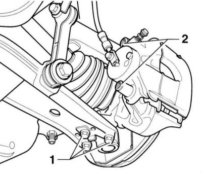
4. Mark the position of the mounting bolts -1- of the ball joint with a felt-tip pen or scriber. Otherwise, when reassembling, the front suspension must be measured and adjusted. Remove bolts -1-.
5. Disconnect the drive shaft from the hub using a puller.
Warning: Do not disconnect the brake hose from the brake caliper. Otherwise, after assembly, air will have to be removed from the system.
6. Depending on the model, various front brake design options can be installed. Caliper FS-III: Remove covers -2- and disconnect the caliper. Suspend the caliper casing on a wire to the chassis. Caliper FN–3: Remove the ribbed bolts from the caliper housing. When installing, they must be replaced with new ones. Remove the caliper, refer to subsection Removal and installation of a brake disk/caliper.
7. Loosen the Phillips head screw and remove the brake disc.
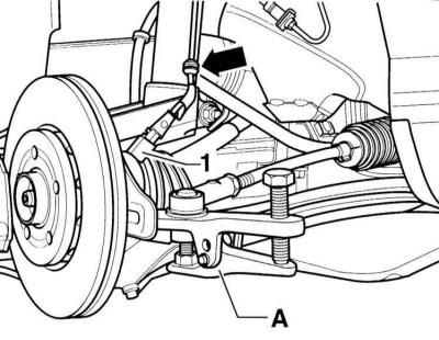
8. Turn away a nut of fastening of the hinge of steering draught to the end of a carving. It acts as a support for the puller.
9. Press Puller (A), eg Hazet 779 tie rod trunnion from arm.
10. Disconnect the connector -1- of the ABS speed sensor.
11. Remove the ABS sensor wire from the holder (arrow).
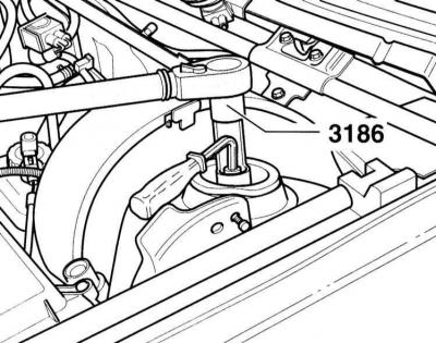
12. Loosen the spring strut mounting nut using AUDI 3186 tool, while holding the rod against turning with a 7 mm Allen key screwdriver. If the specified tool is not available, loosen the nut using an open end wrench. Hazet special tool #2593-21 is available.
13. Pull the suspension strut and wheel bearing housing down through the wheel housing.
14. Separate the wheel bearing housing and suspension strut. To do this, unscrew the bolt securing the suspension strut to the wheel bearing housing.
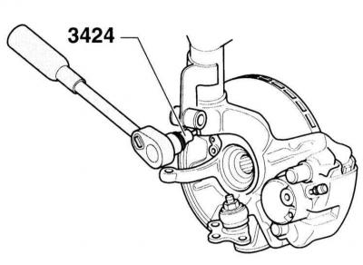
15. Pull the suspension strut up out of the wheel bearing housing. If it is difficult to remove, widen the spline in the wheel bearing housing slightly with AUDI-3424 or some other suitable tool to facilitate removal.
Installation
16. Slide the wheel bearing housing onto the suspension strut so that the holes at the shock absorber tube and the bearing housing match.
17. Insert a new bolt into the bearing housing/suspension strut. The bolt head of the installed spring strut is forward in the direction of travel. Screw on a new self-locking nut and tighten it to a torque of 50 Nm, then turn it 90°with a hard wrench (1/4 turn).
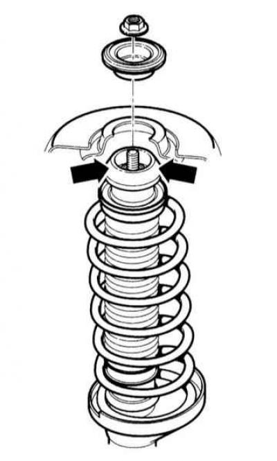
18. Lubricate the strut support with mounting oil before installing the shock absorber «G 294 421 F1» (arrows in the illustration).
19. Insert the suspension strut and fasten it from above with a new nut to a torque of 60 Nm, holding it from turning with a 7 mm Allen key.
Warning: To install a torque wrench, an AUDI-3186 or HAZET 2593-21 can be used as a tool, complete with a 2100-07 anti-rotation tool.
20. Clean the teeth and threads of the drive shaft and the hub with a brush from corrosion and other contaminants.
21. Coat the hex nut and outer pivot teeth on the drive shaft with clean engine oil. Enter as far as possible the outer hinge into the teeth of the hub.
22. Install the brake disc/caliper, refer to subsection Removal and installation of a brake disk/caliper.
Warning: If the pipelines of the brake system were opened, it is necessary to remove air from the latter, refer to subsection Removal of air from the brake system.
23. Dock the ABS speed sensor connector, lay the wire in the holder on the suspension strut.
24. Attach the ball joint to the arm. Install the mounting bolts in the oval holes so that the previously marked markings match. Tighten the bolts to a torque of 20 Nm, then tighten with a hard wrench at an angle of 90° (1/4 turn).
Warning: When installing into a new arm, center the mounting bolts and tighten. Finally, measure the camber, refer to Section 15.
25. Insert the tie rod into the swing arm on the wheel bearing housing and tighten with a new self-locking nut to 45 Nm.
26. Screw on a new hex nut securing the drive shaft to the hub and tighten to 50 Nm. At the same time, ask an assistant to apply the brake so that the hub does not rotate.
27. replace the front wheel so that the markings made during removal match. Pre-lubricate with a thin layer of bearing grease the centering belt of the wheel disk on the hub. Do not grease wheel bolts. Replace rusty bolts. Wrap bolts. Lower the vehicle onto the wheels and tighten the bolts crosswise to 120 Nm.
28. Lower the car on wheels and fix a drive shaft to a nave, address to subsection Removal and installation of power shafts.
Visitor comments