
Front suspension assembly
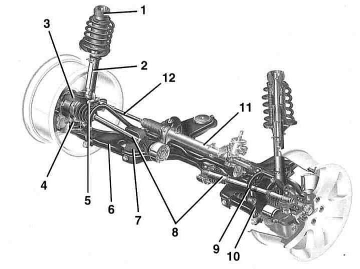
- 1 - shock absorber support
- 2 - shock absorber strut
- 3 - wheel bearing housing
- 4 - wheel drive shaft joint
- 5 - clamp bolt
- 6 - transverse lever
- 7 - unit beam
- 8 - drive shafts
- 9 - anti-roll bar
- 10 - plastic connecting rod
- 11 - steering mechanism
- 12 - steering rod
Front suspension elements
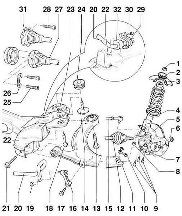
- 1 - flange nut, 60 Nm. Be sure to replace
- 2 - cup
- 3 - body
- 4 - shock absorber strut
- 5 - wheel bearing housing
- 6 - hex nut
- 7 - ball joint. Mark the position. When replacing the suspension arm, install it in the middle of the oval hole and check the track (work of the service station).
- 8 - nut, 45 Nm. Self-locking, must be replaced.
- 9 - bolts, 20 Nm + 90° (1/4 turn). Self-locking, must be replaced.
- 10 - plate with nut
- 11 - transverse lever
- 12 - drive shaft
- 13 - combination bolt, 70 Nm + 90° (1/4 turn). Self-locking, must be replaced.
- 14 - bolt, 100 Nm + 90° (1/4 turn). The threads in the body can be repaired using the Heli-Coil thread insert. The thread length of the repair insert must be equal to the thread length in the body.
- 15 - steering rod
- 15 - connecting rod. Made of plastic.
- 17 - bolt, 45 Nm
- 18 - combination bolt, 100 Nm + 90° (1/4 turn). Self-locking, must be replaced. The separator nut cannot be processed. If there is damage to the nut, the support must be replaced as a set.
- 19 - nut, 30 Nm. Self-locking, must be replaced.
- 20 - stabilizer. For removal and installation it is necessary to lower the unit beam.
- 21 - bolt, 70 Nm + 90° (1/4 turn)
- 22 - unit beam
- 23 - nut. Self-locking, must be replaced.
- 24 - rubber-metal support
- 25 - cylindrical bolts, 40 Nm. M8 x 47.
- 26 - lining
- 27 - shaft with constant velocity joint
- 28 - cylindrical bolts, 40 Nm. M8 x 18.
- 29 - stabilizer clamp
- 30 - bolt, 25 Nm
- 31 - Tripod hinge
- 32 - rubber support
The front suspension is independent. The shock absorber struts of the suspension include a coil spring and a shock absorber. Both shock absorber struts are connected by bolted connections to the body and wheel bearing housings. The wheel bearing housings are controlled through triangular levers connected to the unit beam. The unit beam is connected by bolted connections to the bottom of the car.
The transmission of torque from the engine to the wheels is carried out through two drive shafts, which are connected to the wheels and the main gear by means of two constant velocity joints.
To achieve optimum road properties and minimal tire wear, correct wheel alignment is necessary. In case of excessive tire wear and poor road stability, you should contact a service station where optical wheel alignment can be performed. Measuring the chassis without using appropriate optical methods is impossible.
Warning: Welding and straightening work on the vehicle's wheel-bearing and wheel-guiding structural elements is not permitted. Self-locking nuts and bolts/nuts that are corroded are replaced with new ones in the event of repair.
This article was copied from the website AudiManual