
Table of contents: Removal the front shock absorber… ↓ Replacing the front shock absorber ↓ Removal the front wheel bearing ↓ Replacing the independent axle… ↓ Removal both independent axle… ↓ Removal the (supporting) arms of the… ↓ Dismantling (guides) independent… ↓
Front shock absorber strut parts and their assembly sequence
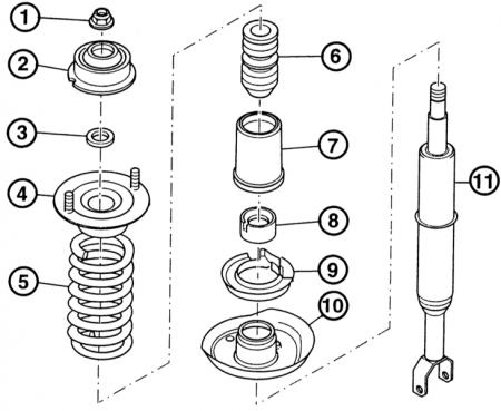
- 1 - nut with flange;
- 2 - shock absorber strut bearing;
- 3 - intermediate washer;
- 4 - upper spring plate;
- 5 - spring;
- 6 - shock absorber buffer;
- 7 - protective shell;
- 8 - protective cap;
- 9 - lower spring pad;
- 10 - lower spring plate;
- 11 - shock absorber.
Removing the shock absorber strut at the top. After removing both protective caps, you can loosen nuts "1" and "2" of the upper rigid mount of the shock absorber strut.
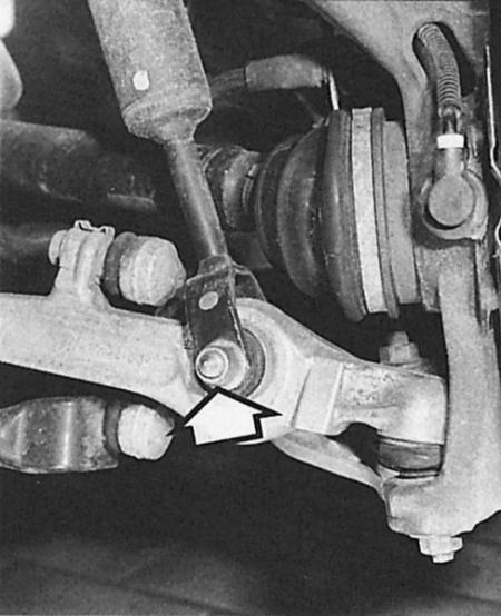
Removing the shock absorber strut at the bottom. The arrow points to the screw connection with the front suspension wishbone at the bottom.
Front shock absorber strut removed

- 1 - Upper shock absorber strut bearing;
- 2 - spring;
- 3 - shock absorber;
- 4 - fork head.
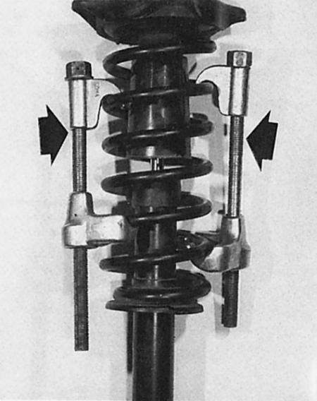
In order to separate the spring from the shock absorber in the dismantled shock absorber strut, spring clamps (arrows) are used.
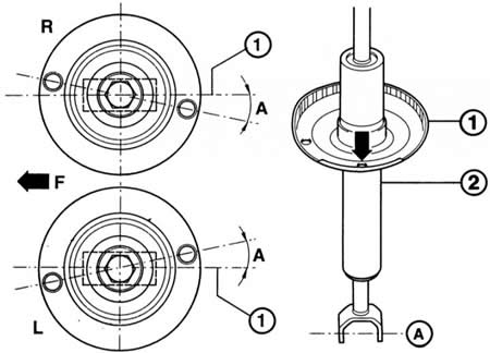
Left: The position of the angle (A) of the upper spring plate on the right (R) and left (L) is mirrored in relation to the screwing axis at the bottom of the fork head (1). The arrow shows the direction of movement (F).
Right: mounting position of the lower spring plate (1) on the shock absorber (2): the hole (arrow) is offset outward by 90° in relation to the screw axis (A).
There are many parts of the front wheel suspension that can be disassembled and assembled independently, although some work requires tools from a workshop. Damaged wheel suspension parts cannot be straightened or even welded, they must only be replaced.
Removal the front shock absorber strut
Removing the shock absorber strut in an Audi A4 is not particularly labor-intensive. It is also nice that you do not have to re-measure the wheel alignment.
1. Purchase new self-locking nuts for the shock absorber strut mounting at the bottom and top, as well as for the upper bearing pivot screw connection.
2. Lift both rubber tips into the humidification reservoir (they cover the upper screw connections of the shock absorber struts).
3. Unscrew both shock absorber strut nuts underneath them.
4. Raise and secure the front of the vehicle.
5. Remove the wheel.
6. Disconnect the wire to the ABS speed sensor on the shock absorber strut.
7. Loosen the upper axle joint clamp bolt nut. Remove the clamp bolt.
8. Remove the axle joints upwards from the wheel bearing housing (steering knuckles). In this case, do not under any circumstances widen the slot in the wheel bearing housing, for example, with a screwdriver.
9. Do not press the tie rod joint.
10. Fold the wheel bearing housing outward.
11. Unscrew the lower screw connection of the shock absorber strut.
12. Carefully remove the shock absorber strut from the wheel arch.
13. Installation: Install the shock absorber so that the hole in the lower spring plate faces the center of the vehicle.
14. Tighten the lower shock absorber mount to 90 Nm.
15. Insert the bearing joints into the wheel bearing housing until they stop.
16. Insert the upper axle joint clamp bolt, tighten the nut to 40 Nm.
17. Re-secure the ABS wire.
18. Tighten the upper shock absorber strut nuts to 20 Nm.
Replacing the front shock absorber
This work, which is carried out on a dismantled shock absorber strut, requires a spring tensioner. At least two tensioners are used; three is better. Without using a tensioner, the nut with the flange at the top of the shock absorber piston rod piston must not be loosened, as the spring is under high pre-tension. The shock absorber strut parts may fly apart in different directions, as if in an explosion - an extreme risk of injury! In addition, a weakened spring cannot be installed.
1. Remove the shock absorber strut.
2. Clamp the shock absorber strut by the fork head in a vice. Never tighten in the area of the cylindrical part, otherwise the shock absorber strut will be compressed.
3. Place the tensioner on the spring coils and compress the spring slightly.
4. To prevent the tensioners from slipping, cover the corresponding spring coils with adhesive tape.
5. Loosen the flange nut on top of the shock absorber strut. Using an Allen key, push the shock absorber piston rod in the opposite direction.
6. Remove the spring with auxiliary parts.
7. Remove the protective cap and the lining under the spring.
8. Use a plastic hammer to pry the spring plate off and remove it.
9. Installation: Place the spring plate onto the new shock absorber.
10. Pay attention to the installation position: the hole in the spring plate must be offset by 90° in relation to the holes in the fork head at the bottom of the shock absorber (permissible deviation of only 2°).
11. Install the spring pad, protective cap and shell, and the thrust shock absorber.
12. Place the spring, which is still under tension, on the plate; make sure that the lower end of the spring coils is in contact with the spring plate stop.
13. Install the upper spring plate with the shock absorber bearing and washer.
14. Tighten the spring plate according to the drawing by 11° to the shock absorber screw-in axis (at the bottom of the forked head). There are different directions on the right and left sides.
15. Work precisely: the tolerance is only 2°.
16. Tighten the flange nut at the top of the shock absorber strut to 60 Nm. Using an Allen key, press the shock absorber piston rod in the opposite direction.
17. Loosen the spring tension, making sure that the end of the spring is in contact with the spring lining stop.
Removal the front wheel bearing
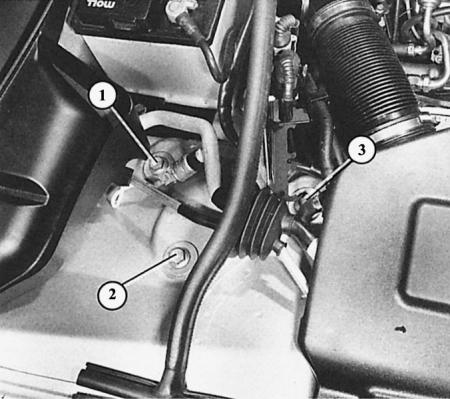
Here the numbers (1–3) indicate the mounting bolts of the upper bracket of the front axle bearing.
The wheel bearing is pressed into the housing with its outer ring, and the wheel hub is pressed into the inner ring of the bearing. A new wheel bearing should never be hammered into the socket, otherwise the next damage will be "mounted together with it". Therefore, the pressing and pressing of the bearing is done by a workshop that has a repair press at its disposal.
Replacing the independent axle suspension arm
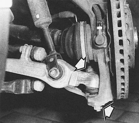
Both arrows point to the so-called flange nuts, which are used to secure the axle joints to the wheel bearing housing.
Bearing hinges (axle joints) on the four suspension arms on each outer side of the front axle cannot be purchased separately, nor can their cuffs. It follows that if a bearing joint is defective, the entire independent suspension arm must be replaced at once.
The situation is different with the rubber-metal bearings on the inside of the axle suspension arms. They can be pressed out and pressed in separately in the workshop. In this case, their installation position must be strictly adhered to. We prefer and describe the replacement as a whole, since pressing must be done in the workshop. In addition, in this case, the axle joint is replaced at the same time, thereby eliminating the next defect in the same unit.
Removal both independent axle suspension arms at the top
1. All axle control arm/bracket bearing support self-locking nuts and bolts must be replaced; buy new ones.
2. First remove the bracket at the top: the car needs to be raised and secured.
3. Unscrew the three bracket mounting bolts in the engine compartment.
4. Remove the wheel.
5. Disconnect the ABS speed sensor wire on the shock absorber strut.
6. Unscrew the nut of the clamping bolt of the upper axle joints. Unscrew the clamping bolt.
7. Remove the axle joints at the top from the wheel bearing housing (steering knuckles). In this case, do not under any circumstances widen the slot of the wheel bearing housing, for example, with a screwdriver.
8. Do not press the tie rod joint.
9. Fold the wheel bearing housing outward.
10. Unscrew the lower screw connection of the shock absorber strut.
11. Carefully remove the shock absorber strut together with the bracket from the wheel arch.
12. Loosen the axle joint screw connections.
13. Installation: Screw on the axle suspension arms, tilting them slightly downwards, so that there is a distance of 55 mm between the outer edge of the bracket and the axle suspension arms (tolerance 2 mm).
14. Tightening torque of the axle suspension arms at the top of the bracket: 50 Nm. Then tighten another 1/4 turn.
15. Reinsert the shock absorber strut with the bracket.
16. Tighten the lower shock absorber mount to 90 Nm.
17. Insert the bearing joints into the wheel bearing housing until they stop.
18. Insert the upper axle joint clamp bolt, tighten the nuts to 40 Nm.
19. Re-secure the ABS wires.
Removal the (supporting) arms of the independent suspension from below
1. Replace all self-locking nuts and axle body/control arm bearing support bolts; the same applies to the flange nut on the outside of the axle joint and the ribbed nuts of the stabilizer connecting rod.
2. Raise the vehicle and secure it.
3. Remove the wheel.
4. Unscrew the flange nut from the outside of the axle joint, press the joint neck out of the conical socket on the wheel bearing housing with a suitable removing device (for example, a large tie rod puller).
5. Unscrew the lower screw connection of the shock absorber strut.
6. Unscrew the ribbed nut of the stabilizer connecting rod and remove the connecting rod.
7. Loosen the axle suspension arm/axle body screw connection.
8. Remove the axle suspension arm.
9. Installation: Clean the axle joint neck. Tighten the axle joint flange nut to 100 Nm.
10. Tighten the lower shock absorber mount to 90 Nm.
11. Reinsert the axle suspension arm/axle body screw connection. Use the inner holes on the body. When tightening, push the axle suspension arm inward. Tighten the nut to 90 Nm. Then tighten it another 1/4 turn.
12. Insert the stabilizer connecting rod (the arrow indicates the direction of movement), tighten the ribbed nut to 90 Nm.
13. The axle suspension arm/axle body bearing support bolt, its self-locking nut and the large unit support bolts, as well as the flange nut on the outside at the axle joint, must be replaced.
Dismantling (guides) independent suspension arms at the bottom
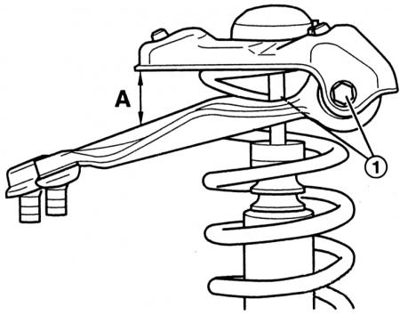
The figure shows the distance "A" at which the upper wishbones of the independent suspension must be removed from the upper bracket (or their convergence line), when tightening the screw connections (1).
1. Raise the vehicle and secure it.
2. Remove the wheel.
3. Unscrew the flange nut from the outside of the axle joint, press the joint neck out of the conical socket on the wheel bearing housing with a suitable removal device (for example, a large tie rod puller).
4. Loosen the axle suspension arm/axle body screw connection.
5. To remove the universal bolt (it cannot be reused), you need to lower the axle body.
6. Therefore, unscrew both smaller hex bolts on the support shields, as well as the larger bolt (unit support bolt).
7. Remove the axle suspension arm.
8. Installation: Clean the axle joint neck. Tighten the axle joint flange nut to 100 Nm.
9. Reinsert the axle suspension arm/axle body screw connection. Use the inner holes on the body. When tightening, push the axle suspension arm inward. Tighten the nut to 90 Nm. Then tighten it another 1/4 turn.
10. Tighten both smaller Allen bolts on the support shields to 25 Nm, the larger bolt (unit support bolt) tighten to 110 Nm. Then tighten it another 1/4 turn.
[The original version of the article is posted on the website: audimanual]