
Table of contents: Removal the rear shock absorbers ↓ Removal the rear shock absorbers ↓ Replacing the rear wheel bearing ↓ Rear wheel bearing adjustment ↓ Wheel bearing of quattro models ↓
Illustration of individual components of the rear shock absorber in the installation sequence in an Audi with front-wheel drive
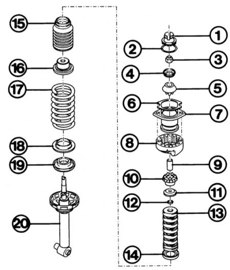
- 1 - cap;
- 2 - cord ring;
- 3 - lock nut;
- 4 - disc washer;
- 5 - support ring;
- 6 - foam pad;
- 7 - upper spring plate;
- 8 - upper spring pad;
- 9 - spacer tube;
- 10 - support ring;
- 11 - washer;
- 12 - ring;
- 13 - rubber shock absorber;
- 14 - receiving ring of the harmonic (15);
- 16 - protective cap;
- 17 - spring;
- 18 - lining;
- 19 - lower spring lining;
- 20 - gas-filled shock absorber.
Mounting position of upper spring plate and cap in front-wheel drive Audi (rear suspension)
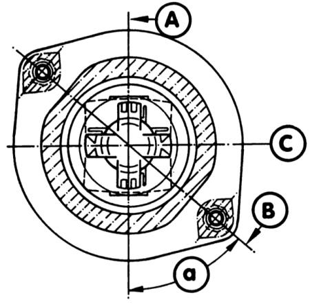
- A - shock absorber eye axis (bottom);
- B - position of threaded studs;
- C - cap axis;
- α is the value of the angle 45°.
Shown here in the assembly sequence are the individual components of the rear shock absorber strut in the Audi A4 quattro
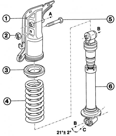
- 1 - shock absorber support;
- 2 - self-locking nut;
- 3 - damping ring;
- 4 - spring;
- 5 - bolt;
- 6 - shock absorber housing.
- 21° - the value of the angular displacement of the upper mount in relation to the lower mount of the shock absorber.
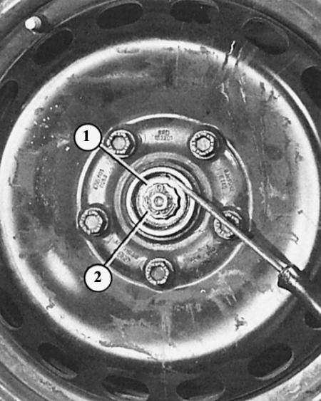
The hub cap can be pressed out by inserting a blunt chisel between the bulge of the hub cap and the hub.
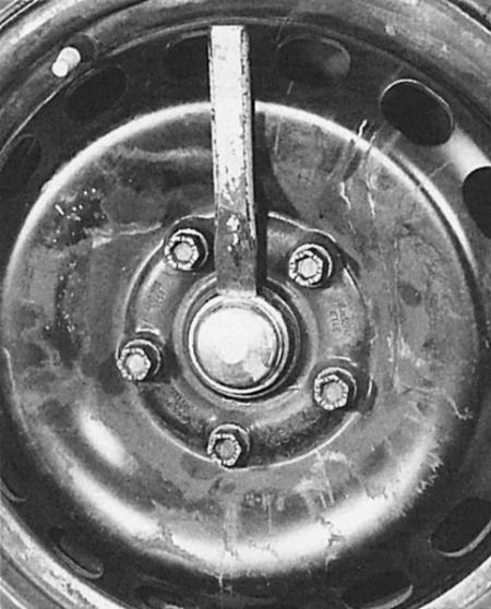
The pressure washer (1) under the adjusting nut (2) should be moved by a screwdriver if the wheel bearing clearance is set correctly. In this case, the blade of the screwdriver must not rest against the brake disc.
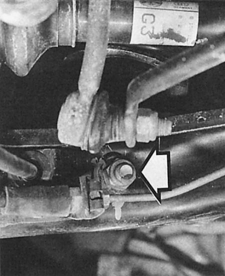
Audi A4 quattro rear suspension
The arrow points to the lower screw connection of the shock absorber strut on the tie rod.
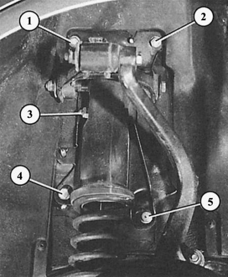
Here the numbers indicate the mounting bolts of the shock absorber strut/wheel arch (1, 2, 4, 5), as well as the upper shock absorber mount (3).
Before replacing the shock absorbers, you need to determine what chassis is installed. Only then can you order the necessary shock absorbers. This can be found out from the sticker with information about the car on the bottom of the trunk or in the recess for the spare wheel.
Legend:
- VA - serial model
- BE - sports chassis
The shock absorber is separated from the dismantled shock absorber strut using a spring tensioner. Such tensioners are sold in the store of related goods. It is important to know that the mounting eye of the shock absorber must be at a certain angle to the upper mount of the shock absorber strut. For its correct installation, the Audi workshop uses a spring tensioner with an angle scale. Without this device, you need to use your instinct and a protractor.
Removal the rear shock absorbers
Front wheel drive cars
Along with the new shock absorbers, a new self-locking nut is also used for the upper shock absorber mount:
1. Remove the shock absorber strut and clamp it in a vice by the lower mounting eye. Do not clamp it in the area of the outer diameter, otherwise it will be pressed through.
2. Place the tensioner on the spring coils and compress the spring slightly.
3. To prevent the tensioner from slipping, cover the corresponding spring coils with adhesive tape.
4. Press down the protective cap, loosen the self-locking nut at the top of the stabilizer connecting rod, while pressing the rod in the opposite direction with an Allen key.
5. After unscrewing the nut, remove the parts of the upper shock absorber support and put them in the order of dismantling.
6. Remove the spring and auxiliary parts from the shock absorber.
7. When assembling, pay attention to the following: the spring base and lining are lubricated with talc and, when assembling, are straightened in the direction of the shock absorber eye.
8. Install the still compressed spring.
9. The color mark on the spring faces down towards the spring plate.
10. When installed correctly, the lower end of the spring will rest against the lining stop.
11. Assemble the parts in the order shown in the figure above.
12. At the top, the end of the spring also fits into the upper recess for the spring eye.
13. Straighten the shock absorber and spring plate at the top as shown in the figure above.
14. Tighten the top mounting nut to 25 Nm.
15. If necessary, move the spring pad at the bottom and the pad on the stop to the end of the spring.
16. Slowly release the spring.
17. Put the cap on top, adjusting its position according to the picture.
18. For information on installing the shock absorber strut, see the previous section.
Removal the rear shock absorbers
Quattro cars
Along with the new shock absorbers, a new self-locking nut and a new bolt for the upper shock absorber mount are also used:
1. Remove the shock absorber strut and clamp it in a vice by the lower mounting eye. Do not clamp it in the area of the outer diameter, otherwise it will be pressed through.
2. Place the tensioner on the spring coils and compress the spring slightly.
3. To prevent the tensioner from slipping, cover the corresponding spring coils with adhesive tape.
4. Loosen the self-locking nut of the upper shock absorber mount and remove the bolt.
5. Remove the shock absorber, spring and damping ring.
6. Install the still compressed spring.
7. The color mark on the spring faces downwards towards the spring plate.
8. The lower end of the spring fits into the recess in the spring eye at the bottom of the shock absorber.
9. At the top, the end of the spring also fits into the recess of the shock absorber ring.
10. Reassemble the shock absorber strut (the spring is still under tension).
11. First loosely screw the upper shock mount to the top of the shock strut by hand (the so-called adapter).
12. Straighten the shock absorber and the upper part of the shock absorber strut so that the imaginary axes of both mounting holes of the shock absorbers are at an angle of 21° to each other (tolerance of only 2°). In this case, the lower hole at the front is turned towards the outer side of the car (see picture top right).
13. In this position, unload the spring.
14. Now tighten the shock absorber mounting bolt nut to 70 Nm. Then tighten it an additional 1/2 turn.
15. For information on installing the shock absorber strut, see the section above.
Replacing the rear wheel bearing
Front wheel drive cars
1. Each side uses one new cotter pin, one inner and one outer bearing, and an O-ring.
2. Raise and secure the vehicle.
3. Remove the brake discs (chapter Brakes), to do this, remove the caliper.
4. Remove the wheel bearing grease cap.
5. Straighten the safety pin and remove it.
6. Remove the castle nut retainer and unscrew the hex nut.
7. Remove the thrust washer and outer wheel bearing.
8. Press out the sealing ring from the rear in the middle of the wheel hub, remove the bearing and wipe off the old grease in the hub.
9. Remove the rotating rings of both bearings from the center of the wheel hub. To do this, place a brass rod from the inside of the rotating ring from different sides and knock it out with soft hammer blows. Make sure that the ring does not bend.
10. Install a new bearing ring on the wheel hub. Place the old bearing ring on top for protection (thick side down) to ensure that careful driving does not cause damage to the working surface of the new bearing.
11. Drive all bearing rings in until they stop.
12. Now remove all the old bearing rings that were installed for protection again.
13. Fill the space between the two bearing rings, as well as the rings and the bearings themselves, with grease.
14. Insert the inner bearing.
15. Using a rubber mallet, tap the sealing ring evenly onto the inside.
16. Slide the wheel hub onto the end of the axle.
17. Install the outer wheel bearing and thrust washer.
18. Hand-tighten the hex nut onto the end of the axle; while doing this, constantly turn the wheel to prevent the bearing from becoming warped.
19. Adjust the wheel bearing (see next section).
20. Install the brake disc and caliper (chapter Brakes). Then press the brake pedal several times.
Rear wheel bearing adjustment
Front wheel drive vehicles
1. Raise the rear of the vehicle and support it.
2. The wheel in cars with steel rims does not need to be removed. If the rims are made of light metals, the wheel must be removed to improve access.
3. Remove the hub cap, cotter pin and crown lock as described above.
4. Tighten the hex nut lightly, rotating the wheel to avoid pinching the bearing.
5. Loosen the nut a little again.
6. The clearance is set correctly if the pressure washer behind the nut can be moved slightly with a screwdriver by pressing hard with your finger. Do not damage the edge of the wheel hub with the screwdriver.
7. If the locking pin can no longer be pushed through the crown stop, turn the nut slightly in the tightening direction.
8. Push the hub cap on using a rubber mallet, placing a rolled up rag between them if necessary.
Wheel bearing of quattro models
The all-wheel drive model has pressed-in double ball bearings on the rear axle as well. They do not require adjustment, but due to the lack of the necessary pressing dies, they cannot be replaced by yourself.