
Table of contents: Replacing the brake lining in ATE ↓ Lucas brake pad replacement ↓ Removal the front brake caliper ↓ Replacing brake piston seals ↓ Replacing the front brake disc ↓
Always replace both pads at the same time, left and right. Use pads with ABE only (General Permit to Operate). If the brake is made by Lucas, then two new self-locking bolts are used when replacing the linings. These are usually included in the brake lining kit - check. If the brake is made by ATE, then the bolts are not needed.
Since the pistons extend further into the brake calipers as the pads wear out, they must be pressed back when installing new, thick pads. In this case, the brake fluid is squeezed out through the pipes into the expansion tank. If brake fluid has been added in vain during this period, the excess must now be sucked out. Otherwise, the brake fluid coming out of the expansion tank will corrode the nearby painted parts in the engine compartment. To suck out, use an absolutely clean pipette or an old injection syringe - never suck out the fluid by mouth!
Replacing the brake lining in ATE
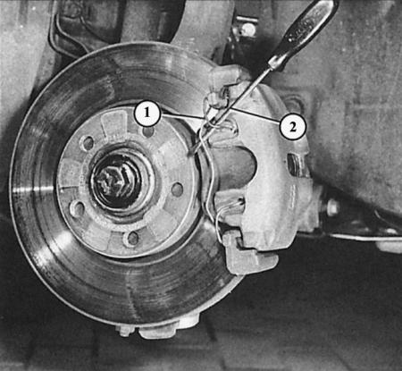
ATE brake: removing the linings, first step: press the mounting spring (1) with a screwdriver (2).
ATE brake: removing the linings, second stage: loosen the Allen bolts in the protective shells (1 and 2) after removing the caps.
Third stage: the outer lining (3) is glued into the ATE brake caliper housing (2), the inner lining (1) is inserted with metal brackets (arrow) into the inner hole of the brake piston.
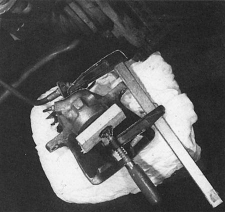
The piston in the brake caliper is pressed down with a clamp. We put a small board between them for protection. The Lucas brake caliper mounted here usually remains fixed at the top.
1. Raise and support the front of the vehicle.
2. Remove the wheel.
3. Turn the steering wheel so that the pads are easily accessible.
4. Use a screwdriver to remove the retaining springs from the outside of the brake caliper.
5. Remove the caps on the inside of the brakes.
6. Insert the Allen key into the now visible Allen key of the guide pins and loosen both pins.
7. Remove the pins and remove the brake caliper housing.
8. Hang the brake caliper body on the wire on the shock absorber strut.
9. Remove the pads on the right and left from the brake caliper housing: the inner pad should be removed with the mounting brackets from the brake piston, the outer pad should be peeled off from the brake caliper – with force if necessary.
10. Press the pistons in the brake caliper with a clamp. To prevent the piston from being warped or damaged, place a small board on the adjacent ring.
11. Carefully remove any remaining adhesive film from the adjacent surface of the outer lining.
12. Clean the brake caliper; there should be no rust, especially on the guides.
13. Insert new pads to glue the outer caliper, remove the protective film from the adhesive area.
14. Install the brake caliper.
15. Tighten the guide pins to 25 Nm and put the caps back on.
16. After assembly, be sure to press the brake pedal several times so that the pads fit against the brake discs. Otherwise, there will be no braking effect!
17. With new pads – if possible – brake carefully for the first 500 km.
Lucas brake pad replacement
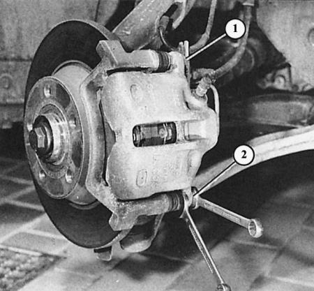
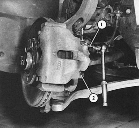
Lucas brake: Unscrew only the lower mounting bolt (2) of the brake caliper housing. Press the guide pin in the opposite direction. The upper mount (1) remains intact.
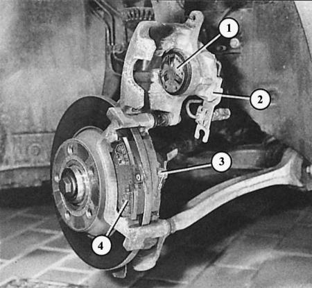
Lucas brake: the caliper body (2) swings upward after loosening the lower mount. The pads (3 and 4) are still in the guides. Further visible: 1 - heat shield in the brake piston.
1. Raise and support the front of the vehicle.
2. Remove the wheel.
3. Turn the steering wheel so that the pads are easily accessible.
4. Unscrew only the lower mounting bolt of the brake caliper housing, while pressing the guide pin by the hexagon in the opposite direction.
5. Fold the brake caliper housing upward.
6. Remove the right and left pads from the guides.
7. Press the piston in the brake caliper with a clamp. To prevent the piston from warping or being damaged, place a small board on the adjacent ring.
8. Ensure that the heat shield is correctly positioned in the brake piston.
9. Insert new pads.
10. Install the brake caliper.
11. Tighten the new (!) lower mounting bolt to 30 Nm. Do not tighten the upper mounting bolt, otherwise the self-locking effect will disappear. Use a narrow open-end wrench to press the guide pin in the opposite direction, otherwise it will jam and the tightening torque will be distorted.
12. After assembly, be sure to press the brake pedal several times so that the pads fit against the brake discs. Otherwise, there will be no braking effect!
13. With new pads – if possible – brake carefully for the first 500 km.
Removal the front brake caliper
The front brake calipers are attached to the shock absorber strut with so-called ribbed bolts. These bolts have a ribbed surface behind the hex head, preventing the bolt from loosening unintentionally. These bolts should never be replaced with regular bolts!
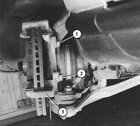
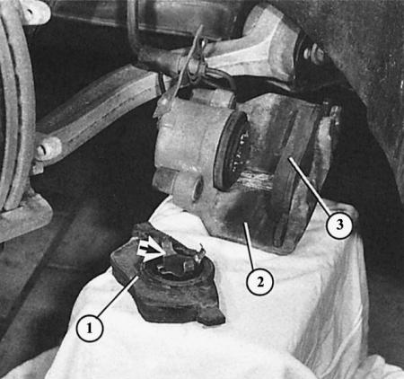
Here you can see the brake caliper support (3) with the brake caliper housing removed. The numbers "1" and "2" indicate the brake caliper mounting bolts (knurled bolts).
1. Unscrew the wheel.
2. Remove the brake pads from the brake calipers (as described in the previous sections).
3. Hang the brake caliper body with the brake hose screwed on so that the hose is not stretched.
4. Or unscrew the brake hose or tube. In this case, press the brake pedal and hold it so that the brake fluid does not leak out.
5. Unscrew the brake caliper mounting bolts on the brake support.
6. Before installation, clean the knurled surfaces of the ribbed bolts.
7. Tighten the rib bolts to 125 Nm.
8. Screw the brake hose or brake pipe back on.
9. Bleed the brake system if the brake hose or brake pipe was unscrewed.
10. Before the first meters of movement, press the brake pedal several times to adjust the normal pedal clearance.
Replacing brake piston seals
If the brake piston seal in the caliper is damaged, you need to take care of replacing it as soon as possible, otherwise the piston will soon jam due to dirt and corrosion. Seals are sold only assembled with a brake piston gasket ring. To install both parts, you need to push the piston out of the brake caliper. For safety reasons, this work should be done in a workshop. Depending on the circumstances, also dismantle the brake caliper itself and take it for repair.
Replacing the front brake disc
Brake discs should be replaced on both sides at once. Replacing one side may result in uneven braking effect.
1. Completely remove the brake caliper as described and secure it to the body with wire. The hydraulic hose remains connected.
2. The brake disc can only be removed from the wheel hub by hand.
3. If it is rusted, then help yourself with strong blows of a hammer, but only if the disk is going to be changed.
4. Before installing a new brake disc, clean the mating surface on the wheel hub.