



Table of contents: FS-III support ↓ Removal ↓ Installation ↓ Support FN–3 ↓ Removal ↓ Installation ↓
Front brakes FS– III
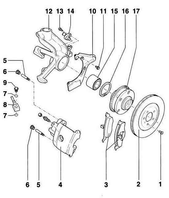
- 1 - Phillips head screw
- 2 - brake disc. Replace only as a set on the entire axle. To remove, first disconnect the caliper.
- 3 - brake pads. All 4 pads on one axle must be replaced.
- 4 - support
- 5 - guide pin, 30 Nm
- 6 - lid
- 7 - sealing ring. Be sure to replace.
- 8 - brake hose. No need to unscrew to replace the pads.
- 9 - hollow bolt, 35 Nm
- 10 - shield
- 11 - bolt, 7 Nm
- 12 - wheel bearing housing
- 13 - Allen screw, 8 Nm
- 14 - ABS speed sensor. Before installation, clean the intake hole and lubricate with AUDIG000650 grease
- 15 - wheel bearing
- 16 - retaining ring
- 17 - Hub with rotor. Note: All externally located bolts have an anti-corrosion coating. Therefore, only original spare mounting bolts should be used.
Front brake mechanism. Caliper FN– 3
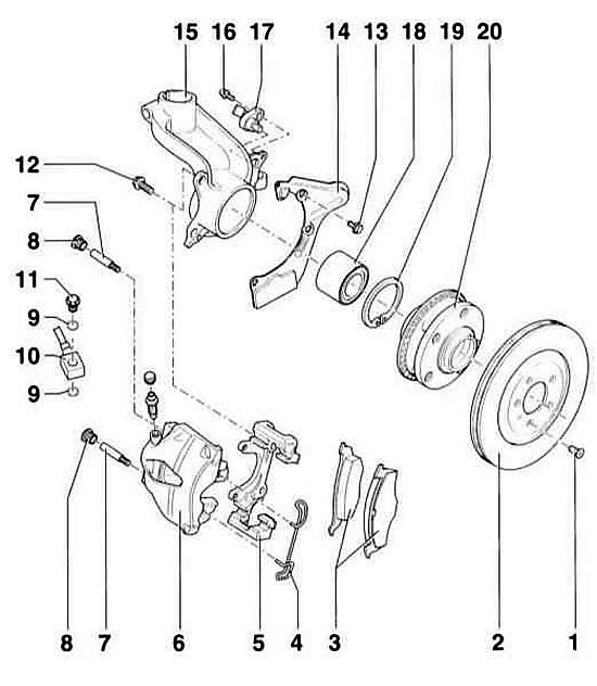
- 1 - Phillips head screw
- 2 - brake disc. Replace only as a set on the axle. To remove, first disconnect the caliper.
- 3 - brake pads. The outer brake pad has a film glued to the back side. After installing the pad, the film must be removed. Replace only as a set on the entire axle.
Note: Before installing new pads, thoroughly clean the calipers from dirt (degrease). In this case, pay special attention to removing any remaining film on the adjacent surfaces of the outer pads.
- 4 - Stopper. Insert into both holes of the caliper body.
- 5 - guide. Replace damaged covers. The repair kit contains a pad with grease. It should be used to lubricate the guide pins.
- 6 - caliper body
- 7 - guide pin, 30 Nm
- 8 - lid
- 9 - sealing ring. Be sure to replace.
- 10 - brake hose. No need to unscrew to replace the pads.
- 11 - hollow bolt, 35 Nm
- 12 - ribbed bolt, 125 Nm. Clean the mating surface and threads before installation.
- 13 - bolt, 7 Nm
- 14 - shield
- 15 - wheel bearing housing
- 16 - Allen screw, 8 Nm
- 17 - ABS speed sensor. Before installation, clean the intake hole and lubricate with AUDIG000650 grease
- 18 - wheel bearing
- 19 - retaining ring
- 20 - Hub with rotor. Note: All external bolts have an anti-corrosion coating. Therefore, only original spare mounting bolts should be used.
FS-III support
Warning: All external bolts are coated with anti-corrosion coating. Therefore, only genuine replacement bolts should be used.
Warning: There are two different versions of the front wheel brake. Therefore, use the illustration to find out which version is installed on your car.
Removal
Warning: Brake pads are subject to the General Admission Rules (ABE). In addition, they are intended by the manufacturer to be installed on a specific vehicle model. Therefore, it is recommended to use only brake pads approved by the manufacturer.
1. Mark the position of the corresponding front wheel relative to the hub with paint. This will allow the balanced wheel to be installed in its original position during assembly. Loosen the wheel mounting bolts with the vehicle on the ground. Raise the front of the vehicle, place it on stands, and remove the front wheel.
Warning: If the brake pads are to be reinstalled, they must be marked before removal. Do not switch the brake pads from the outside to the inside or vice versa, or from the left wheel to the right. Always replace all front pads at the same time, even if only one has reached the wear limit.
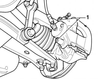
2. Remove the caps – 1 – from both guide pins. Unscrew both guide pins with a socket wrench.
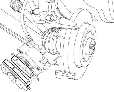
3. Secure the caliper to the suspension with wire.
Warning: Do not lower the caliper as this may cause the brake hose to be pulled out.
4. Remove the brake pads.
Installation
Warning: Do not press the brake pedal with the pads removed. Otherwise, the piston will be pushed out of the housing. In this case, remove the caliper as a set and insert it into place at a service station.
5. Clean the guide surfaces and the shoe seating areas in the shaft with a rag and alcohol. Do not use solvents containing mineral oils or tools with sharp edges.
Warning: Use only alcohol to clean the brake.
6. Before installing the pads, check the brake disc by feeling it with your fingers. If there are any burrs, the brake disc can be ground down (work of the service station), if it is still thick enough.
7. Measure the thickness of the disc, referring to the subsection Checking the thickness of the brake disc.
8. Check for cracks on the piston dust boot. If there is damage, replace the dust boot immediately, as any dirt that has penetrated quickly causes the caliper to lose its tightness. The caliper must be disassembled for this purpose (work of the service station).
Warning: If the brake pads are significantly worn, check the ease of movement of the piston. To do this, insert a wooden block into the caliper and ask an assistant to slowly press the brake pedal. The piston should move easily in both directions. To check, you need to install another caliper. Be careful not to completely push out the piston. If the piston moves hard, the caliper is subject to repair (work of the service station).
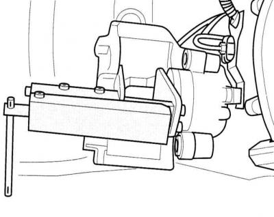
9. Use the tool to push the piston back. This can also be done using a block of hardwood (hammer handles). In doing so, make sure that the piston does not become warped and that the piston and dust boot surfaces are not damaged.
Warning: When the piston is pressed, brake fluid is squeezed into the reservoir. Monitor the flow of fluid into the reservoir. Remove excess if necessary.
Warning: To suck out brake fluid, use a plastic bottle that is intended only for this purpose. Do not use a drinking bottle for this! Brake fluid is poisonous. Never suck it out with your mouth through a hose. Use a siphon for this purpose. After replacing the brake pads, the fluid level in the reservoir should not exceed the MAX mark on the reservoir, because the brake fluid expands when heated. The leaking fluid flows down the brake cylinder, destroying the coating and causing corrosion.
10. Insert the brake pads into the caliper guides.
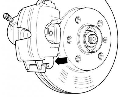
11. Install the caliper from the bottom first (arrow on the illustration).
Caution: The caliper journal (arrow) must be positioned behind the wheel bearing housing guide.
12. Secure the caliper with both guide pins to the wheel bearing housing with a torque of 30 Nm.
13. Install both finger covers.
14. Install both front wheels so that the markings applied during removal match. Tighten the wheel mounting bolts. Lower the car onto the wheels and tighten the wheel mounting bolts crosswise to a torque of 120 Nm.
Warning: Press the brake pedal hard several times until you feel a distinct resistance in the pedal. This will cause the pads to settle onto the brake disc and take their place.
15. Check the brake fluid level in the reservoir. If necessary, top up to the MAX mark.
16. Carefully allow the new brake pads to break in. To do this, brake the car several times from 80 to 40 km/h, pressing the pedal lightly. Allow the brake to cool between braking.
Warning: After installing new pads, they must be run in. To do this, when driving the first 200 km, do not brake the car hard unless necessary.
Warning: In some regions, brake pads must be disposed of as special material. Local authorities must inform drivers of permitted disposal sites.
Warning: Please perform a reliability check:
- Are the brake hose fasteners tightened securely?
- Is the brake hose secured in the holder?
- Are the air bleed nipples tightened?
- Is there enough brake fluid in the reservoir?
- With the engine running, check the tightness of the system. To do this, press the brake pedal with a force of 200-300 N (20-30 kg) for 10 s. The pedal should not move. Check all connections for tightness.
Support FN–3
Removal
Warning: Brake pads are subject to the General Admission Rules (ABE). In addition, they are intended by the manufacturer to be installed on a specific vehicle model. Therefore, it is recommended to use only brake pads approved by the manufacturer.
17. Mark the position of the corresponding front wheel relative to the hub with paint. This will allow the balanced wheel to be installed in its original position during assembly. Loosen the wheel mounting bolts with the vehicle on the ground. Raise the front of the vehicle, place it on stands, and remove the front wheel.
Warning: If the brake pads are to be reinstalled, they must be marked before removal. Do not switch the brake pads from the outside to the inside or vice versa, or from the left wheel to the right. Always replace all front pads at the same time, even if only one has reached the wear limit.
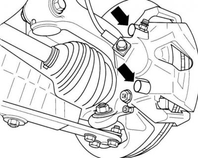
18. Remove the covers –1– from both guide pins. Unscrew both guide pins with an Allen key.
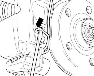
19. Use a screwdriver to pry up and remove the brake shoe retainers.
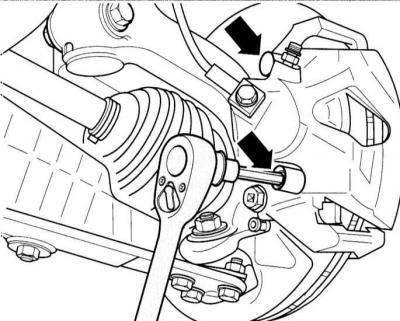
20. Remove both guide pins from the caliper.
21. Remove the caliper and tie it to the body with wire.
Warning: Do not lower the caliper as this may cause the brake hose to be pulled out.
22. Remove the outer shoe from the brake shield.
23. Remove the inner shoe (with a lock) from the piston.
Installation
Warning: Do not press the brake pedal with the pads removed. Otherwise, the piston will be pushed out of the housing. In this case, remove the caliper as a set and insert it into place at a service station.
24. Clean the guide surfaces and the shoe seating areas in the shaft with a rag and alcohol. Do not use solvents containing mineral oils or tools with sharp edges.
Warning: Use only alcohol to clean the brake.
25. Before installing the pads, check the brake disc by feeling it with your fingers. If there are any burrs, the brake disc can be ground down (work of the service station), if it is still thick enough.
26. Measure the thickness of the disc, referring to the subsection Checking the thickness of the brake disc.
27. Check for cracks on the piston dust boot. If there is damage, replace the dust boot immediately, as any dirt that has penetrated quickly causes the caliper to lose its tightness. The caliper must be disassembled for this purpose (work of the service station).
Warning: If the brake pads are significantly worn, check the ease of movement of the piston. To do this, insert a wooden block into the caliper and ask an assistant to slowly press the brake pedal. The piston should move easily in both directions. To check, you need to install another caliper. Be careful not to completely push out the piston. If the piston moves hard, the caliper is subject to repair (work of the service station).
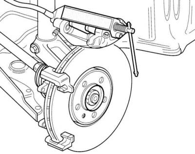
28. Use the tool to push the piston in. This can also be done using a block of hardwood (hammer handles). In doing so, make sure that the piston does not become warped and that the piston and dust boot surfaces are not damaged.
Warning: When you press the piston, brake fluid is forced into the reservoir. Monitor the flow of fluid into the reservoir. Remove excess if necessary.
Warning: To suck out brake fluid, use a plastic bottle that is intended only for this purpose. Do not use a drinking bottle for this! Brake fluid is poisonous. Never suck it out with your mouth through a hose. Use a siphon for this purpose. After replacing the brake pads, the fluid level in the reservoir should not exceed the MAX mark on the reservoir, as the brake fluid expands when heated. The leaking fluid flows down the brake cylinder, destroying the coating and causing corrosion.
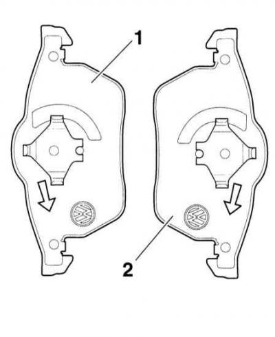
29. Insert the inner brake shoe (with a lock) into the brake piston.
Warning: Inner brake shoe (with a lock) has an arrow, refer to the accompanying illustration. The arrow should point in the direction of rotation of the brake disc when the vehicle is moving forward. If installed incorrectly, (to the other side of the car) this may result in noise.
30. Install the outer brake shoe onto the guide.
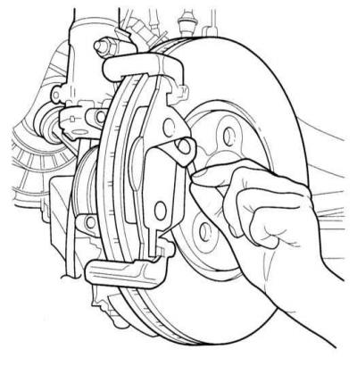
31. Remove the protective film from the back plate of the outer brake shoe.
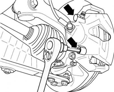
32. Install the caliper and secure it with both guide pins to the guide with a torque of 30 Nm.
33. Install both finger covers.
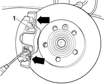
34. Insert the retainer –1– into the caliper.
Warning: After installation in both holes, the retainer must be pressed under the guide. If installed incorrectly, the outer shoe will not install despite wear, which will lead to an increase in pedal travel.
35. Install both front wheels so that the markings applied during removal match. Tighten the wheel mounting bolts. Lower the car onto the wheels and tighten the wheel mounting bolts crosswise to a torque of 120 Nm.
Warning: Press the brake pedal hard several times until you feel a distinct resistance in the pedal. This will cause the pads to settle onto the brake disc and take their place.
36. Check the brake fluid level in the reservoir. If necessary, top up to the MAX mark.
37. Carefully allow the new brake pads to break in. To do this, brake the car several times from 80 to 40 km/h, pressing the pedal lightly. Allow the brake to cool between braking.
Warning: After installing new pads, they must be run in. To do this, when driving the first 200 km, do not brake the car hard unless necessary.
Warning: In some regions, brake pads must be disposed of as special material. Local authorities must inform drivers of permitted disposal sites.
Warning: Please perform a reliability check:
- Are the brake hose fasteners tightened securely?
- Is the brake hose secured in the holder?
- Are the air bleed nipples tightened?
- Is there enough brake fluid in the reservoir?
With the engine running, check the tightness of the system. To do this, press the brake pedal with a force of 200-300 N (20-30 kg) for 10 s. The pedal should not move. Check all connections for tightness.