Repair Chevrolet Repair Toyota Repair Honda Repair AvtoVAZ Repair Mercedes-Benz Repair BMW Repair Opel
Home  |  Contacts  |  Sitemap  |    
English Русский
Български
Беларускі
Український
Српски
Hrvatski
Română
Polski
Slovenský
Magyar
AudiManual.ru


  • AUDI 80
  • AUDI 100
  • AUDI A3
  • AUDI A4
  • AUDI A6
  • AUDI A8
  • AUDI Q
  • OTHER
  • ARTICLES
C4 (1990-1994) C4 (1990-1994, petrol) C3 (1982-1990) C3 (1982-1990, petrol) C3 (1982-1990, diesel)

Front Brake Disc Pads — Checking and Replacing (Audi 100 C3)

  • Home
  • Audi 100
  • C3 (1982-1990, diesel)
  • Chassis
  • Brake system
  • Front Brake Disc Pads — Checking and Replacing
            0
Table of contents: Girling support ↓ Teves support ↓
1. Jack up the car. Remove both front wheels.

2. Check the brake pad thickness by looking through the slot in front of the caliper body. If the shim thickness on any pad is equal to or below the minimum specified thickness, all four pads must be replaced.

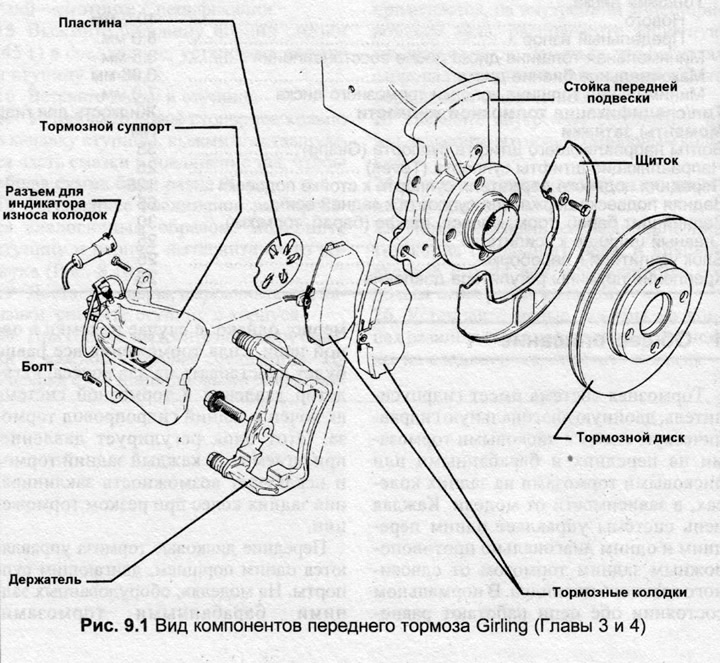
Girling support


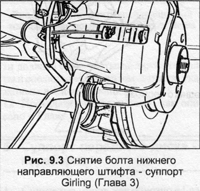
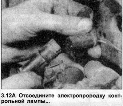
3. Disconnect the brake pad wear indicator wiring connector and, using a suitable wrench, remove the lower guide pin bolt.

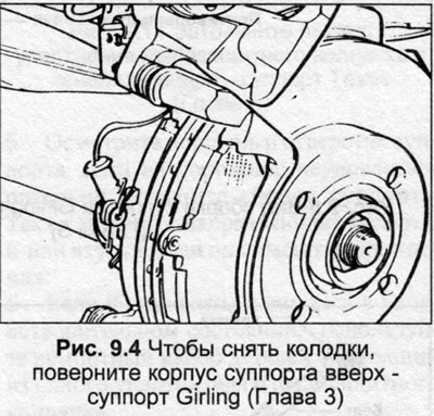
4. Turn the caliper body upward, take out the two brake disc pads, remove the piston heat shield. If the pads are to be reinstalled, mark them so that they can be installed in their original positions.

5. Clean dust and dirt from the caliper, piston, disc and pads.

6. Rotate the brake disc by hand to remove rust and deposits. Carefully inspect the entire disc surface and if there are deep cracks or excessive wear, the disc should be replaced. Also inspect the caliper for fluid leaks around the piston, corrosion, or other damage. Replace the piston seals or caliper body as needed.

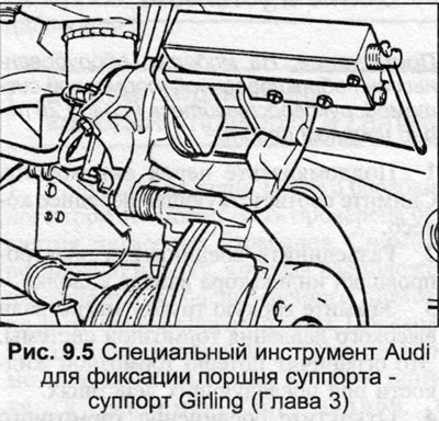
7. If new pads are being installed, first push the piston back into the bore using a G-clamp or suitable block as a lever. When doing this, be careful not to overflow the brake fluid reservoir, drain some if necessary.

8. Place the new heat shield on the piston, then place the pads in their original positions against the disc.

9. Place the caliper body onto the pads and install the new guide pin bolt, tightening it to the torque specified in Specifications.

10. Connect the brake pad wear indicator wiring, install the wheels and lower the vehicle.


11. Press the brake pedal several times until the piston rests against the pads, then check and, if necessary, add fluid to the master cylinder reservoir.

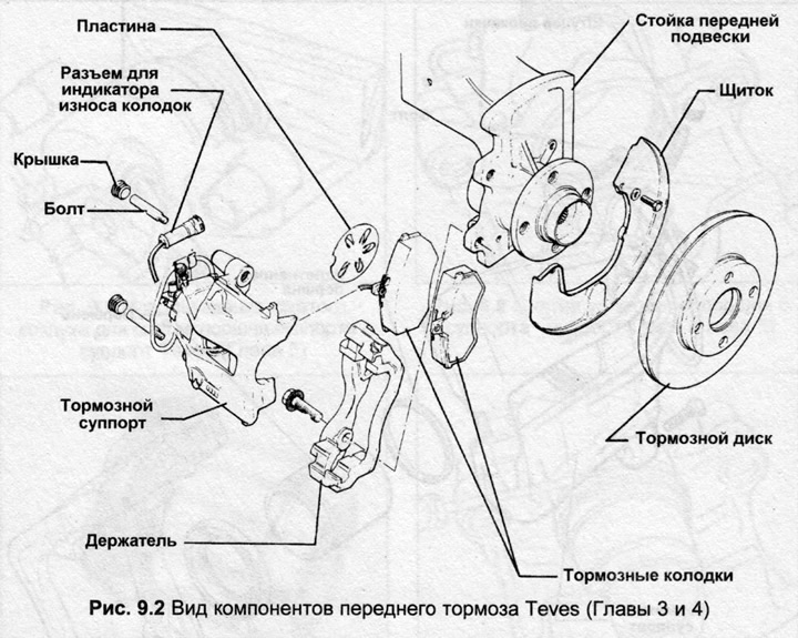
Teves support


12. Disconnect the connector of the brake pad wear indicator wiring, remove the plastic covers of the guide bolts (photo).
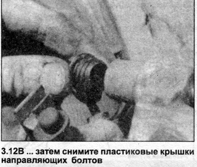
12. Disconnect the connector of the brake pad wear indicator wiring, remove the plastic covers of…


12. Disconnect the connector of the brake pad wear indicator wiring, remove the plastic covers of…


13. Remove the upper and lower guide bolts, lift the caliper body (photo). Secure the caliper using twine or wire. Do not let it hang unsupported.
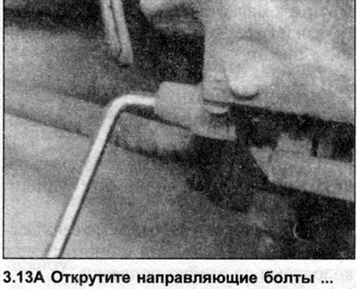
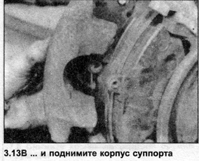
13. Remove the upper and lower guide bolts, lift the caliper body (photo). Secure the caliper using…


13. Remove the upper and lower guide bolts, lift the caliper body (photo). Secure the caliper using…


14. Remove the two brake disc pads from the mounting bracket (photo). If the pads are to be reused, mark them so that they can be installed in their original positions.
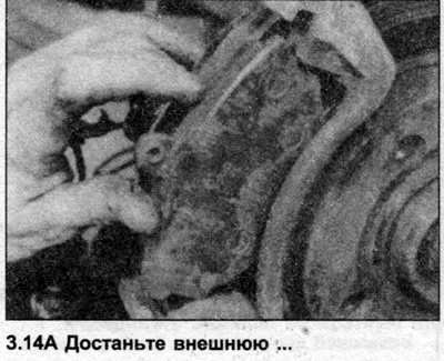
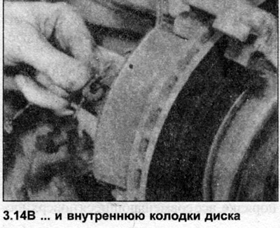

14. Remove the two brake disc pads from the mounting bracket (photo). If the pads are to be reused,…


14. Remove the two brake disc pads from the mounting bracket (photo). If the pads are to be reused,…


15. Before installing the pads, see points 5, 6 and 7.

16. Place the pads in position on the bracket hanger, install the caliper body.

17. Insert the guide bolts and tighten them to the tightening torque specified in Specifications.

18. Install the guide bolt covers, connect the wear indicator wiring.

19. Install the wheels and lower the vehicle.

20. Press the brake pedal several times until the piston rests against the pads, then check and, if necessary, add fluid to the master cylinder reservoir.
20. Press the brake pedal several times until the piston rests against the pads, then check and, if…


20. Press the brake pedal several times until the piston rests against the pads, then check and, if…


20. Press the brake pedal several times until the piston rests against the pads, then check and, if…


20. Press the brake pedal several times until the piston rests against the pads, then check and, if…


20. Press the brake pedal several times until the piston rests against the pads, then check and, if…
The article was checked by auto expert Nikita Rudakov
This article is available at russian, bulgarian, belarusian, ukrainian, serbian, croatian, romanian, polish, slovak, hungarian

Share information:
Previous articles
Audi 100 C3: Brake system
Next articles

Maintenance and inspection
General description
Brake system specifications
Front Disc Support — Removal and Installation
Front Disc Support — Overhaul
Front brake disc — removal and installation
Rear Brake Pads — Checking and Removing


Similar articles on other Audi car models:
Replacing the front brake pads of the ATE brand Audi 80 B2 (1979-1986)
Replacing the front brake pads Audi A3 Type 8L (1996-2003)
Measuring the thickness of the front disc brake pads Audi A4 B5 (1994-2001, petrol)
Replacing the front brake pads Audi A6 C5 (1997-2004)
Checking the front brake pads Audi A8 D2 (1994-2002)
Front brake pads FBC-60. Removal Audi Q5 Type 8R (2008-2017)
Brake mechanism with floating caliper, front brake disc Audi A2 (1999-2005)
Link to this page in different formats


Visitor comments

No comments yet


How much will 46 + 43 =


100(C4, 1990-1994) 
  • General information
  • User manual
  • Power unit
  • Engine repair
  • Ignition system
  • Fuel system (gasoline)
  • Fuel system (diesel)
  • Lubrication system
  • Cooling system
  • Exhaust system
  • Transmission
  • Clutch
  • Car gearbox
  • Drive shafts
  • Chassis
  • Car suspension
  • Steering
  • Wheels and tires
  • Brake system
  • Body
  • Ventilation and heating
  • Body repair
  • Electrical equipment
  • Power devices
  • Lighting and appliances
  • Electrical circuits
 
100(C4, 1990-1994, petrol) 
  • General information
  • Operation and maintenance
  • Power unit
  • Engine repair
  • Exhaust system
  • Cooling system
  • Supply system
  • Air filter
  • Mono-Motronic injection system
  • Digifant injection system
  • KE-III-Jetronic and KE-Motronic
  • MPI and MPFI injection system
  • Transmission
  • Clutch
  • Car gearbox
  • Chassis
  • Suspension and steering
  • Brake system
  • Wheels and tires
  • Body
  • Exterior
  • Interior
  • Electrical equipment
  • Fuses and relays
  • Power devices
  • Ignition system
  • Lighting and signaling
  • Equipment and devices
  • Electrical circuits
 
100(C3, 1982-1990) 
  • General information
  • User manual
  • Maintenance
  • Specifications
  • Power unit
  • Engines 4-cylinder
  • Engines 5-cylinder
  • Diesel engine
  • Cooling system
  • Power system (carburetor)
  • Power system (injector)
  • Fuel system (diesel)
  • Transistor ignition system
  • Electronic ignition system
  • Transmission
  • Clutch
  • 4 speed gearbox 014
  • 5 speed gearbox 013 and 093
  • 5 speed gearbox 016 and 012
  • Shift mechanism KP 016
  • Automatic transmission
  • Front wheel drive
  • Chassis
  • Front suspension
  • Rear suspension
  • Steering
  • Brake system
  • Body
  • Body elements
  • Electrical equipment
  • Lighting and appliances
  • Power devices
  • Electrical circuits
 
100(C3, 1982-1990, petrol) 
  • General information
  • Maintenance and operation
  • 4 cylinder engine
  • Engine repair
  • Cooling and lubrication system
  • Supply system
  • Ignition system
  • 5 cylinder engine
  • Engine repair
  • Cooling and lubrication system
  • Supply system
  • Ignition system
  • Transmission
  • Clutch and drive shafts
  • 4 speed gearbox 014
  • 5 speed gearbox 013 and 093
  • 5 speed gearbox 016 and 012
  • Automatic gearbox
  • Chassis
  • Steering
  • Front suspension
  • Rear suspension
  • Brake system
  • Body
  • Body elements
  • Doors, locks and windows
  • Body repair
  • Electrical equipment
  • Equipment and devices
  • Power devices
  • Electrical circuits
 
100(C3, 1982-1990, diesel) 
  • General information
  • User manual
  • Maintenance
  • Troubleshooting
  • Power unit
  • Engine in a car
  • Engine removed
  • Cooling system
  • Fuel system
  • Exhaust system
  • Starting and charging
  • Preheating
  • Transmission
  • Clutch
  • Mechanical gearbox
  • Automatic gearbox
  • Drive shafts
  • Chassis
  • Brake system
  • Suspension
  • Steering
  • Body
  • Exterior
  • Interior
  • Electrical equipment
  • Equipment and devices
  • Electrical circuits
 
AudiManual.ru © 2017-2026 · Mobile version · Feedback · Sitemap: EN BG BY UA RS HR RO PL SK HU · Site search · News and articles
80 B2 · 80 B3 petrol · 80 B3 · 80 B4 · 100 C3 diesel · 100 C3 petrol · 100 C3 · 100 C4 petrol · 100 C4 · A3 Type 8L · A4 B5 petrol · A4 B5 · A4 B6 petrol · A4 B6 · A4 B7 · A4 B8 · A6 C4 · A6 C5 · A6 C5 Allroad · A8 D2 · Q5 Type 8R · Q7 Typ 4L · Audi A2 ·
This site uses cookies 🍪. Click the button to accept this fact.