
2. Block the front wheels, jack up the rear of the car, secure it on axle stands. Remove the rear wheels, release the handbrake.
3. Remove the cover in the center of the brake drum.
4. Remove the pin and remove the locking ring.
5. Unscrew the nut and remove the thrust washer.
6. Remove the brake drum, being careful not to disturb the outer wheel bearing. If the brake drum is stuck on the shoes, insert a screwdriver through the hole under the wheel bolt and press the wedge to release the shoes.
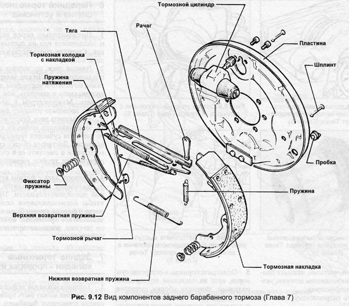
7. Note the position of the brake shoes and springs.
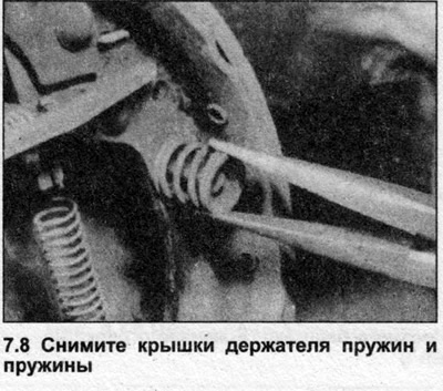
8. Press the spring holder cover, turn it 90° and remove it together with the springs (photo).
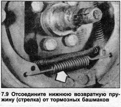
9. Disconnect the lower return spring from the pads (photo).
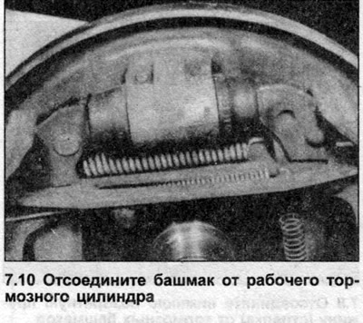
10. Separate the lower shoe from the anchor, release the upper shoe from the working brake cylinder, and turn until the rear part of the shoes appears (photo).
11. Disconnect the handbrake cable.
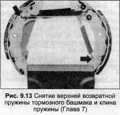
12. Disconnect the upper return spring and wedge spring.
13. Separate the second brake shoe from the first brake shoe and pusher.
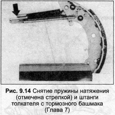
14. Disconnect the tensioner, springs and remove the pusher from the first brake shoe together with the wedge.
15. Clean dust from the brake drum, brake shoes and shield.
16. Measure the brake shoe lining thickness. If it is worn to the minimum value, replace all four rear brake shoes.
17. Clean the drum brake shield. If there are grease stains from the hub bearings, the seal must be replaced. If fluid is leaking from the wheel cylinder, it must be rebuilt or replaced as described in Chapter 8. Do not press the brake pedal with the pads removed. Place a rubber band on the pistons of the wheel cylinder to secure them.
18. Lubricate the contact surfaces of the handbrake lever and push rod.
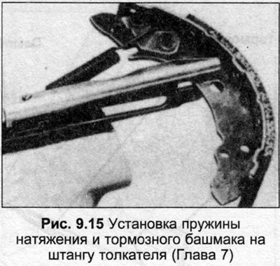
19. Clamp the pusher, place the tension spring on the pusher and the first brake shoe, place the shoe groove in the pusher.
20. Place a wedge between the shoe and the pusher.
21. Position the handbrake lever on the second brake shoe in the pushrod, install the upper return spring.
22. Connect the handbrake cable to the lever, turn the shoes up and position the top of the shoes on the brake cylinder pistons.
23. Install the lower return spring, then the lower shoe lever onto the anchor.
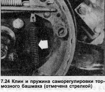
24. Install the spring on the wedge and the primary shoe (photo).
25. Install the retaining springs and covers.
26. Press the wedge upward to create maximum clearance between the pads.
27. Install the brake drum, adjust the wheel bearings as described in Section 10.
28. Press the brake pedal fully once to adjust the rear brakes.
(Read the original source on the website: AudiManual)