



Select function "053. Parking brake". Select function "006. Basic setting".
Indication on the tester display: in the indication field "1" a request to enter the indication group appears; The input keyboard is displayed in the display field "2".
Enter the number "007" for the "indication group number" from the input keyboard into the display field "2" and confirm the entry by pressing the Q button. (piston backward movement). To exit the input mask, press the green "arrow" button at the bottom left. Switch off the ignition. Raise the car. Remove the wheels. Disconnect the brake hose and electrical wiring from the combined bracket on the wheel support. Loosen the brake caliper housing mounting screws, holding the guide pins.
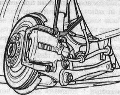
Do not apply tension to the brake hose or electrical cables. Remove the brake caliper. Do not hang the brake caliper from the brake hose, but secure it to the body using a suitable cable tie or wire. Do not load the brake hose with the weight of the brake caliper. Do not press the brake pedal with the brake caliper removed. Remove the brake pads. Remove the pad support plates. Press in the piston. Use the T10145 piston pressing tool for this.
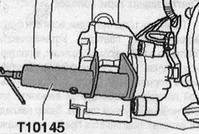
Do not tilt the brake piston when recessing it.
Installation
Use only alcohol to clean the brake caliper housing. Insert the brake pad retaining springs. Remove the protective film from the rear brake pad plate (if available).
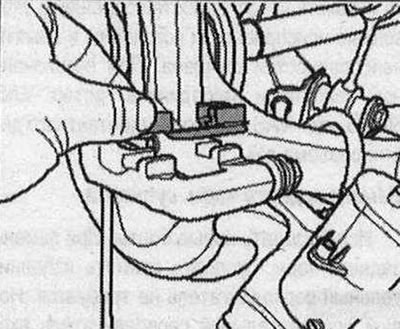
Insert brake pads
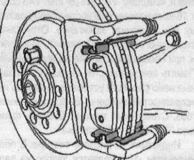
Make sure that the torm is properly planted. pads on the support plates of the "strelka" pads.
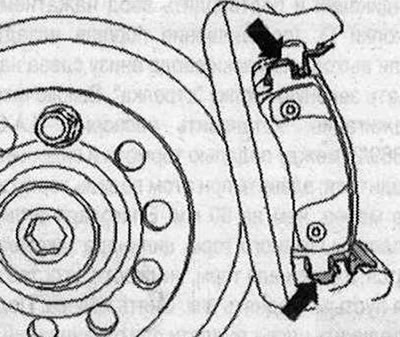
The brake pads must be positioned between both tongues of the pad backing plate to maintain an air gap between the brake disc and the brake pad. Install the brake caliper. The repair kit contains new self-locking bolts that must be installed. Secure the brake caliper with new self-locking bolts. Use a torque wrench with a socket to tighten the bolts "V.A.G 1331/3". Fasten the brake hose and electrical wiring in the combined bracket on the wheel support. Check that the brake hose and electrical cable are correctly fastened in the bracket of the wheel bearing housing. Spontaneous separation of the brake hose and electrical cable from the bracket is not allowed. Install the wheels. Lower the car. Tightening torque of the wheel bolts. Check the brake fluid level, top up if necessary. Turn on the ignition.
Indication on the tester display: In the indication field "1" a request appears to enter the indication group; The input keyboard is displayed in the display field "2".
Enter the number "006" for the "indication group number" from the input keyboard into the display field "2" and confirm the entry by pressing the Q button. (bring the pistons together). To exit the input mask, press the green "arrow" button at the bottom left. The fault memory is interrogated, the indicated faults are eliminated and the fault memory is cleared. With the ignition off, disconnect the "VAS 5051 B" or "VAS 5052" tester from the 16-pin diagnostic connector of the vehicle.