



Removal
Caution: If brake pads are to be reinstalled, they must be marked before removal. Always replace all pads on one axle of the vehicle, even if only one pad has reached the wear limit.
Mark the position of the rear wheels in relation to the hubs with paint. This is necessary for reinstalling the wheels in their original position, as a result of which their balance is maintained. With the car standing on its wheels, loosen the rear wheel mounting bolts. Raise the rear of the car and secure it on stands, unscrew the bolts and remove the rear wheels.
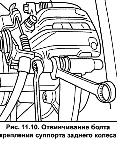
Remove the upper and lower rear wheel caliper mounting bolts, using a second wrench to hold the guide pin from turning (see fig. 11.10).
Remove the caliper and tie it to the rear strut with soft wire, making sure the caliper does not hang on the brake hose, or become stretched or twisted.
Remove the brake pads.
Installation
Caution: Do not press the brake pedal with the brake pads removed, otherwise the piston will be forced out of the caliper.
Use a rag and alcohol to remove dust and dirt from the bearing surface and the pad installation area. Do not use solvents containing mineral oils or sharp tools.
If the pads are fit for further use, clean them using a wire brush and rag.
Check the brake disc for cracks, especially around the holes for the wheel mounting bolts, as well as for wear or mechanical damage and, if necessary, regrind it, provided that the thickness of the disc after processing is within the normal range.
Measure the thickness of the brake disc and replace it if necessary.
Check the caliper piston dust cover for cracks. If not, replace the cover immediately, as dirt that has penetrated the cylinder will compromise the caliper's seal. To do this work, you must disassemble the caliper.
When installing new brake pads, it is necessary to screw the piston into the caliper.
Attention. When screwing in the piston, the brake fluid is forced out of the brake cylinder into the refill tank, so constantly monitor the fluid level in the tank, and if necessary, pump out a small amount of it from the tank.
Safety instructions
When pumping out brake fluid, use a deaeration bottle or plastic bottle; which are intended only for working with brake fluid. Brake fluid is poisonous, so it cannot be sucked out by mouth through a hose. For this, use a bellows. After replacing the brake pads, the brake fluid level in the replenishing tank should not exceed the "MAX" mark, since the volume of brake fluid increases when heated. Excess brake fluid leaking out gets on the master brake cylinder, destroys the varnish coating and promotes corrosion.
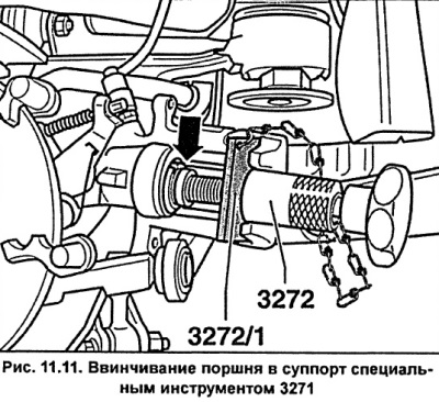
To screw the piston into the cylinder, install tool 3272 on the caliper so that the tool flange is installed in the piston grooves and accordingly fits against tool 3272/1. Rotate the knurled roller of the tool to the left until it stops. By turning the handle of the special tool to the right, screw the piston into the caliper. If screwing in the piston is difficult, install a 13 mm spanner on the splines at the base of the handle and screw in the piston using the spanner (see fig. 11.11).
If you don't have a special tool, screw the piston into the caliper using steel plates inserted into the piston grooves. Press firmly on the plates and screw the piston in.
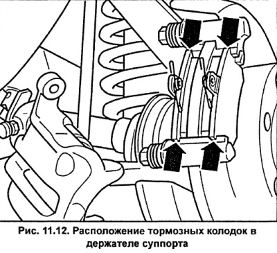
Remove the protective film from the base of the new brake pads and install the brake pads into the caliper holder (see fig. 11.12). If old pads are being installed, check that they are installed in their original position.
Install the caliper and secure it with new self-locking bolts, screwing them into the guide pins and tightening them to a torque of 35 Nm.
Please note: Each original brake pad set comes with four new self-locking bolts.
Apply a thin layer of grease to the flange that centers the wheel disc. Install the wheel, aligning the previously applied marks, and secure it with bolts. Lower the car to the ground and tighten the wheel mounting bolts to a torque of 120 Nm.
Caution: Press the brake pedal several times to press the brake pads against the brake disc.
Check the brake fluid level in the reservoir and top it up to normal if necessary.
Attach the parking brake cable to the caliper.
Carefully allow the new brake pads to become acclimated to the brake disc. To do this, brake the car several times from 80 km/h to 40 km/h. Allow the brakes to cool between braking operations.
After installing new brake pads, avoid sudden braking during the first 200 km of the vehicle's mileage.
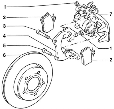
Fig. 11.9. Rear brake caliper
1 - self-locking bolt, 35 Nm,
A new bolt must be used during installation.
When unscrewing the bolt, hold the guide pin from turning.
2 - brake pads,
Replace brake pads as a set on one axle of the vehicle.
3 - bolt with ribbed head base, 95 Nm,
4 - caliper holder with guide pins and protective covers,
Supplied complete as a spare part, with sufficient grease on the guide pins. If the protective cover is damaged, a complete spare set should be installed.
5 - bolt with ribbed head base, 95 Nm,
6 - brake disc,
It is necessary to replace both brake discs on one axle of the vehicle.
7 - support