Repair Chevrolet Repair Toyota Repair Honda Repair AvtoVAZ Repair Mercedes-Benz Repair BMW Repair Opel
Home  |  Contacts  |  Sitemap  |    
English Русский
Български
Беларускі
Український
Српски
Hrvatski
Română
Polski
Slovenský
Magyar
AudiManual.ru


  • AUDI 80
  • AUDI 100
  • AUDI A3
  • AUDI A4
  • AUDI A6
  • AUDI A8
  • AUDI Q
  • OTHER
  • ARTICLES
C5 Allroad (1999-2005) C5 (1997-2004) C4 (1994-1997)

Brake disc (Audi A6 C5)

  • Home
  • Audi A6
  • C5 (1997-2004)
  • Chassis
  • Brake system
  • Brake disc
            0
Table of contents: Removal ↓ Installation ↓

Removal


Use paint to mark the position of the wheel relative to the hub. This is necessary to reinstall the wheel in its original position, which maintains its balance.

With the vehicle standing on its wheels, loosen the wheel mounting bolts.

Raise the relevant part of the car and secure it on stands, unscrew the bolts and remove the wheel.

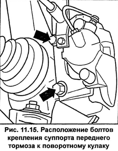
Unscrew the two bolts shown by the arrows in Figure 11.15 and remove the caliper assembly from the brake disc. The figure shows the front caliper. To remove the rear caliper, unscrew the two Allen-head bolts.

Unscrew the two bolts shown by the arrows in Figure 11.15 and remove the caliper assembly from the…


Remove the brake hose from the bracket.

Raise the caliper and use soft wire to tie it to the front strut, making sure the caliper does not hang on the brake hose, or become stretched or twisted.

Caution: Do not unscrew the brake hose, otherwise you will have to bleed the air from the hydraulic brake system after assembly.


If the caliper needs to be removed, follow these steps.

On the front wheel caliper, clean the area around the junction of the brake hose and brake pipe and unscrew the brake pipe from the brake hose coupling. Close the holes in the brake hose and pipe with suitable plugs.


On the rear wheel caliper, clean the area around the junction of the brake hose and the brake pipe and unscrew the brake pipe at the brake hose connection and, if necessary, unscrew the brake hose from the caliper. Close the holes in the brake hose and pipe with suitable plugs.

Caution. When opening the hydraulic brake, brake fluid leaks out. To reduce brake fluid loss, remove the cap from the brake system refill tank, cover the tank neck with polyethylene and screw the cap back on. This is necessary to ensure that the cap seals the refill tank tightly.


Remove the brake disc.

Installation


Note: If it is necessary to replace the brake disc, the second brake disc must also be replaced to ensure uniform braking. When replacing the brake discs, the brake pads must also be replaced.


Check and, if necessary, clean the mating surfaces of the brake disc and hub. When installing a new brake disc, remove the protective coating from its surface.

Install the brake disc onto the wheel hub.

Install the caliper with brake pads. Do not twist the brake hose. Check that when the front wheel is fully turned, the brake hose does not contact the front suspension elements and the body.

Secure the brake hose to the bracket.

Secure the caliper with bolts and tighten the front caliper mounting bolts FN-3 to 120 Nm and the caliper HP-2 to 190 Nm. If bolts with a ribbed head base are reinstalled, clean the ribbed surface using a wire brush.

Secure the rear caliper with the bolts, tightening them to a torque of 95 Nm. If re-installing bolts with a ribbed head base, use a wire brush to clean the ribbed surface.


If the brake hose was disconnected, screw it back into place.

Remove the polyethylene from the filler neck of the replenishment tank and bleed the corresponding brake circuit.

Connect the parking brake cable to the rear brake caliper.

Apply a thin layer of grease to the flange that centers the wheel disc. Install the wheel, aligning the previously applied marks, and secure it with bolts. Lower the car to the ground and tighten the wheel mounting bolts to a torque of 120 Nm.

Caution: Press the brake pedal several times to press the brake pads against the brake disc.


Check the brake fluid level in the reservoir and top it up to normal if necessary.

Text provided by the online resource: AUDIMANUAL
The article was checked by auto expert Alexey Ivanov
This article is available at russian, bulgarian, belarusian, ukrainian, serbian, croatian, romanian, polish, slovak, hungarian

Share information:
Previous articles
Audi A6 C5: Brake system
Next articles

Checking the thickness of the brake disc
Replacing rear brake pads
Replacing the front brake pads
General information
Brake fluid
Bleeding the hydraulic brake system
Brake hoses
Brake light switch


Similar articles on other Audi car models:
Removal and installation the front brake disc of the Girling… Audi 80 B2 (1979-1986)
Front Brake Disc Pads — Checking and Replacing Audi 100 C3 (1982-1990, diesel)
Checking the thickness of the brake disc Audi A3 Type 8L (1996-2003)
Measuring the thickness of the front disc brake pads Audi A4 B5 (1994-2001, petrol)
Brake disc Audi A8 D2 (1994-2002)
Front brake disc FBC-60. Replace brakes Audi Q5 Type 8R (2008-2017)
Brake mechanism with floating caliper, front brake disc Audi A2 (1999-2005)
Link to this page in different formats


Visitor comments

No comments yet


How much will 18 + 21 =


A6(C5 AR, 1999-2005) 
  • General information
  • User manual
  • Maintenance
  • Troubleshooting
  • Power unit
  • V6 petrol engines
  • V8 petrol engines
  • Diesel engines
  • Cooling and heating system
  • Injection system (gasoline)
  • Fuel system (diesel)
  • Supply system
  • Exhaust system
  • Ignition system
  • Transmission
  • Clutch
  • Mechanical gearbox
  • Automatic gearbox
  • Chassis
  • Brake system
  • Car suspension
  • Steering
  • Body
  • Body elements
  • Doors, locks and windows
  • Electrical equipment
  • Equipment and devices
  • Power devices
  • Electrical circuits
  • Schemes (petrol engine 2.7 l)
  • Schemes (petrol engine 4.2 l)
  • Schemes (diesel engine 2.5 l)
 
A6(C5, 1997-2004) 
  • General information
  • User manual
  • Maintenance
  • Power unit
  • Engine repair
  • Cooling system
  • Fuel system
  • Engine management
  • Fuel system (diesel)
  • Exhaust system
  • Transmission
  • Clutch
  • Car gearbox
  • Chassis
  • Front suspension
  • Rear suspension
  • Steering
  • Wheels and tires
  • Brake system
  • Body
  • Exterior
  • Interior
  • Electrical equipment
  • Air conditioner
  • Equipment and devices
  • Electrical circuits
 
A6(C4, 1994-1997) 
  • General information
  • User manual
  • Maintenance (gasoline)
  • Maintenance (Diesel)
  • Gasoline engines
  • 4 cylinder engines
  • 5 cylinder engines
  • 6 cylinder engines
  • Diesel engines
  • 4 cylinder engines
  • 5 cylinder engines
  • Engine repair
  • Removal and reassembly
  • Cooling system
  • Single point injection system
  • Multipoint injection system
  • MPI/MPFI injection system
  • Fuel system (diesel)
  • Exhaust system
  • Ignition system
  • Transmission
  • Clutch
  • Manual transmission
  • Automatic transmission
  • Drive shafts
  • Chassis
  • Brake system
  • Front suspension
  • Rear suspension
  • Steering
  • Body
  • Exterior (external elements)
  • Interior (internal elements)
  • Electrical equipment
  • Power devices
  • Lighting and appliances
  • Electrical circuits
 
AudiManual.ru © 2017-2026 · Mobile version · Feedback · Sitemap: EN BG BY UA RS HR RO PL SK HU · Site search · News and articles
80 B2 · 80 B3 petrol · 80 B3 · 80 B4 · 100 C3 diesel · 100 C3 petrol · 100 C3 · 100 C4 petrol · 100 C4 · A3 Type 8L · A4 B5 petrol · A4 B5 · A4 B6 petrol · A4 B6 · A4 B7 · A4 B8 · A6 C4 · A6 C5 · A6 C5 Allroad · A8 D2 · Q5 Type 8R · Q7 Typ 4L · Audi A2 ·
This site uses cookies 🍪. Click the button to accept this fact.