Repair Chevrolet Repair Toyota Repair Honda Repair AvtoVAZ Repair Mercedes-Benz Repair BMW Repair Opel
Home  |  Contacts  |  Sitemap  |    
English Русский
Български
Беларускі
Український
Српски
Hrvatski
Română
Polski
Slovenský
Magyar
AudiManual.ru


  • AUDI 80
  • AUDI 100
  • AUDI A3
  • AUDI A4
  • AUDI A6
  • AUDI A8
  • AUDI Q
  • OTHER
  • ARTICLES
C5 Allroad (1999-2005) C5 (1997-2004) C4 (1994-1997)

Bleeding the hydraulic brake system (Audi A6 C5)

  • Home
  • Audi A6
  • C5 (1997-2004)
  • Chassis
  • Brake system
  • Bleeding the hydraulic brake system
            0
Bleeding the hydraulic brake system is necessary to remove air, which significantly reduces braking efficiency. Air can enter the hydraulic system due to depressurization of the system during repairs, replacement of individual units or brake fluid. The presence of air in the drive is indicated by an increased travel of the brake pedal and its softness. Before removing air, check the tightness of all brake drive units and their connections.

Usually, bleeding is done with a special device. However, the brake system can be bled using the brake pedal, for this you will need an assistant.

If bleeding of the entire system is required, each wheel brake cylinder must be bled.

If only a partial disconnection of the hydraulic brake system was made and the appropriate precautions were taken, it is sufficient to bleed only that part of the system.

Note: If one of the sections of the brake fluid replenishment bank is found to be without brake fluid (for example, in case of leaks in the brake system), for safety reasons, it is necessary to bleed the entire brake system. Bleeding sequence: 1. Right rear caliper; 2. Left rear caliper; 3. Right front caliper; 4. Left front caliper.


Attention
  • The bleed nipples must be opened very carefully to avoid breaking them. It is recommended to apply a rust-corrosive agent to the nipples about two hours before bleeding.
  • If the bleed nipples turn with difficulty, the brake system must be bled at a service station. During bleeding, it is necessary to monitor the brake fluid level in the replenishment tank.
  • The fluid level should not reach the bottom of the refill tank, as air will enter the system through the refill tank. Add only fresh brake fluid.

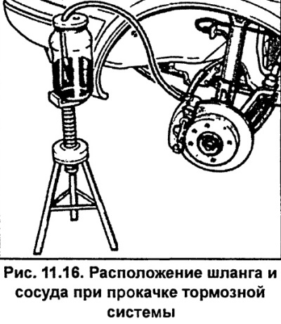
  • Remove the dust cap from the wheel cylinder bleeder nipple, clean it and put a clean transparent hose on it, the other end of which is lowered into a container partially filled with brake fluid. The container should be at least 300 mm above the bleeder nipple. This prevents air from entering the cylinder through the thread of the bleeder nipple.
  • The assistant should press the brake pedal 3-5 times with an interval of 2-3 seconds to increase the pressure in the brake system. When pressing, an ever-increasing resistance of the brake pedal should be felt.
  • Once sufficient pressure has been reached, press the brake pedal all the way down and hold it in this position.
  • Using a spanner, loosen the bleed nipple half a turn.
  • While continuing to press the pedal, force the fluid in the system together with the air through the hose into the container. At the same time, make sure that the end of the hose is constantly in the container, below the level of the brake fluid (see fig. 11.16).
  • Once the pedal reaches the extreme forward position and the fluid stops flowing out through the hose, tighten the bleed nipple until it stops
  • Repeat these operations on this brake cylinder until air stops escaping from the hose.
  • Wipe the bleed nipple clean and install the protective cap.
  • Repeat these operations for the other wheels.
  • If there is no air in the brake system, the pedal should travel about half of its travel. To eliminate the influence of the brake booster on the bleeding of the brakes, bleed the air with the engine not running.

If there is no air in the brake system, the pedal should travel about half of its travel. To…
The article was checked by auto expert Alexey Ivanov
This article is available at russian, bulgarian, belarusian, ukrainian, serbian, croatian, romanian, polish, slovak, hungarian

Share information:
Previous articles
Audi A6 C5: Brake system
Next articles

Brake fluid
Brake disc
Checking the thickness of the brake disc
Replacing rear brake pads
Brake hoses
Brake light switch
Checking the brake booster
Parking brake lever


Similar articles on other Audi car models:
Bleeding the brake hydraulic system Audi 80 B2 (1979-1986)
Bleeding the brake hydraulic system Audi 100 C3 (1982-1990, petrol)
Bleeding air from the clutch hydraulic system Audi A3 Type 8L (1996-2003)
Bleeding the brake system Audi A4 B5 (1994-2001, petrol)
Bleeding the hydraulic brake drive Audi A8 D2 (1994-2002)
Replacing brake fluid, bleeding the brake system Audi Q7 Typ 4L (2005-2015, diesel)
Hydraulic clutch drive system Audi A2 (1999-2005)
Link to this page in different formats


Visitor comments

No comments yet


How much will 28 + 40 =


A6(C5 AR, 1999-2005) 
  • General information
  • User manual
  • Maintenance
  • Troubleshooting
  • Power unit
  • V6 petrol engines
  • V8 petrol engines
  • Diesel engines
  • Cooling and heating system
  • Injection system (gasoline)
  • Fuel system (diesel)
  • Supply system
  • Exhaust system
  • Ignition system
  • Transmission
  • Clutch
  • Mechanical gearbox
  • Automatic gearbox
  • Chassis
  • Brake system
  • Car suspension
  • Steering
  • Body
  • Body elements
  • Doors, locks and windows
  • Electrical equipment
  • Equipment and devices
  • Power devices
  • Electrical circuits
  • Schemes (petrol engine 2.7 l)
  • Schemes (petrol engine 4.2 l)
  • Schemes (diesel engine 2.5 l)
 
A6(C5, 1997-2004) 
  • General information
  • User manual
  • Maintenance
  • Power unit
  • Engine repair
  • Cooling system
  • Fuel system
  • Engine management
  • Fuel system (diesel)
  • Exhaust system
  • Transmission
  • Clutch
  • Car gearbox
  • Chassis
  • Front suspension
  • Rear suspension
  • Steering
  • Wheels and tires
  • Brake system
  • Body
  • Exterior
  • Interior
  • Electrical equipment
  • Air conditioner
  • Equipment and devices
  • Electrical circuits
 
A6(C4, 1994-1997) 
  • General information
  • User manual
  • Maintenance (gasoline)
  • Maintenance (Diesel)
  • Gasoline engines
  • 4 cylinder engines
  • 5 cylinder engines
  • 6 cylinder engines
  • Diesel engines
  • 4 cylinder engines
  • 5 cylinder engines
  • Engine repair
  • Removal and reassembly
  • Cooling system
  • Single point injection system
  • Multipoint injection system
  • MPI/MPFI injection system
  • Fuel system (diesel)
  • Exhaust system
  • Ignition system
  • Transmission
  • Clutch
  • Manual transmission
  • Automatic transmission
  • Drive shafts
  • Chassis
  • Brake system
  • Front suspension
  • Rear suspension
  • Steering
  • Body
  • Exterior (external elements)
  • Interior (internal elements)
  • Electrical equipment
  • Power devices
  • Lighting and appliances
  • Electrical circuits
 
AudiManual.ru © 2017-2026 · Mobile version · Feedback · Sitemap: EN BG BY UA RS HR RO PL SK HU · Site search · News and articles
80 B2 · 80 B3 petrol · 80 B3 · 80 B4 · 100 C3 diesel · 100 C3 petrol · 100 C3 · 100 C4 petrol · 100 C4 · A3 Type 8L · A4 B5 petrol · A4 B5 · A4 B6 petrol · A4 B6 · A4 B7 · A4 B8 · A6 C4 · A6 C5 · A6 C5 Allroad · A8 D2 · Q5 Type 8R · Q7 Typ 4L · Audi A2 ·
This site uses cookies 🍪. Click the button to accept this fact.