
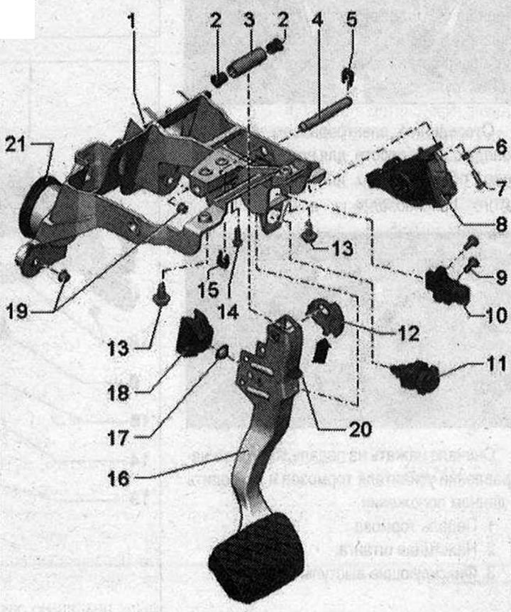
II 1. Pedal assembly support bracket (the picture shows a car with an automatic transmission); 2. Bushing; 3. Brake pedal axle; 4. Support finger; 5. Lock washer (spring steel), right; 6. Glass; 7. Accelerator pedal module mounting bolt. 8 Nm; 8. Gas pedal assembly; 9. Bolt. 8 Nm; 10. Brake pedal position sensor "G100" (only for vehicles with hybrid drive); 11. Brake light sensor; 12. Fastening the electromagnet (only for vehicles with hybrid drive); 13. Pedal support bolt. 20 Nm; 14. The pin bolt holds the pin in the correct position. 8 Nm; 15. Lock washer (spring steel), left; 16. Brake pedal. If possible, leave the brake pedal stop in place; abrupt release of the brake pedal may cause damage to the brake light sensor bracket; 17. The bearing shell is connected; rivets with fastening. For the ball head of the brake booster push rod; 18. Stop. For the ball head of the brake booster push rod with ball head locking protrusions; 19. Nut. 8 Nm; 20. Emphasis; 21. Nozzle (installed only on cars with automatic transmission)
(The original source of the article can be found on the website «AudiManual.ru»)