
Table of contents: Brake pedal and support bracket… ↓ Disconnecting and connecting the… ↓ Removal and installation the brake… ↓ Removal and installation the brake… ↓ Removal and installation the support… ↓
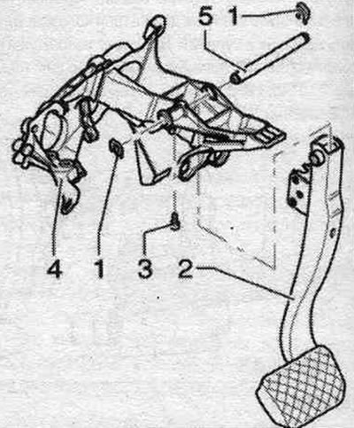
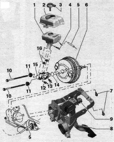
Brake pedal and support bracket components and assemblies
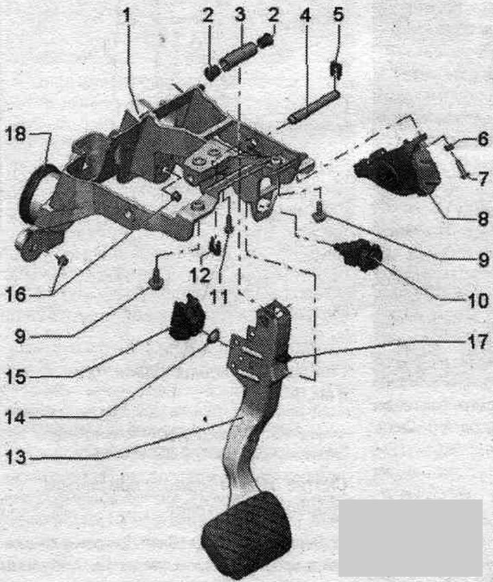
1. Pedal assembly support bracket.
2. Bushing.
3. Brake pedal axle.
4. Axis.
5. Lock washer (spring steel), right.
6. Washer.
7. Accelerator pedal module screw: 8 Nm.
8. Accelerator pedal module.
9. Support bracket screw: 20 Nm.
10. Brake light switch.
11. Axle bolt: The bolt secures the axle, 8 Nm.
12. Lock washer (spring steel), left.
13. Brake pedal. If possible, do not remove the brake pedal support, as the brake light switch socket may be damaged if the brake pedal is moved abruptly when unlocking.
14. Push rod socket insert: for the spherical head of the brake booster piston rod.
15. Fastening: for the spherical head of the brake booster piston rod; with clamps for the spherical head.
16. Nut: 8 Nm.
17. Emphasis.
18. Bushing: installed only on vehicles with automatic transmission.
Disconnecting and connecting the brake pedal and brake booster
Disconnecting the brake pedal from the brake booster
If possible, do not remove the brake pedal support, as the brake light switch socket may be damaged if the brake pedal is moved abruptly when unlocking.
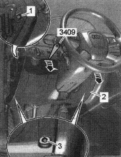
Remove storage compartments from the driver's side "1...3".
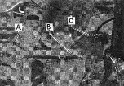
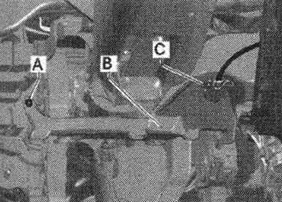
Disconnect connector "C" from the air duct of the air duct. for legs. Remove the air duct "A-B". Remove the brake light switch.
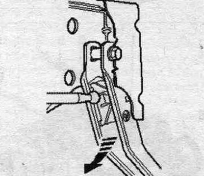
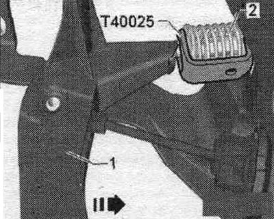
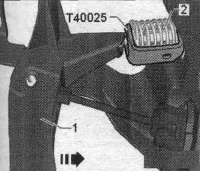
Press the brake pedal towards the brake booster and hold it in this position.
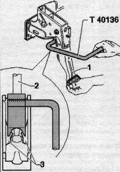
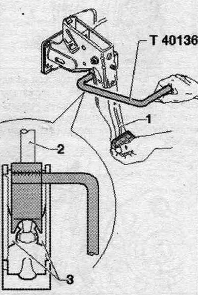
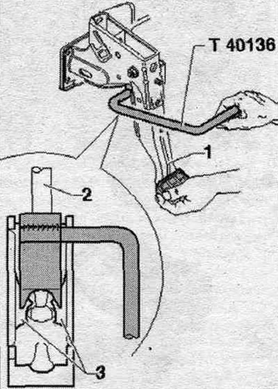
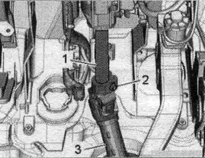
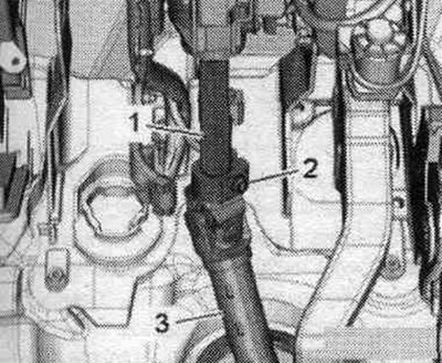
1. Brake pedal. 2. Rod. 3. Locking protrusions.
Install the T40136 puller as shown and pull it towards the driver while holding the brake pedal (when performing this operation, the pedal should not move back). In this case, the locking pins "3" in the socket of the ball head of the rod "2" are pressed. For clarity, this operation is shown with the pedal assembly disassembled. Pull the puller "T40136" together with the pedal itself towards the driver's seat (This will disengage the brake pedal from the spherical end of the rod).
Connecting the brake pedal to the brake booster
If possible, do not remove the stop "17" from the brake pedal, since the socket of the brake light switch "10" may be damaged if the brake pedal is moved abruptly when unlocking. Align the ball head with the push rod socket, press the brake pedal towards the brake booster, the ball head will enter and install in the socket with a clearly audible click. Install the brake light switch.
Install the air duct for blowing space. for legs "A-B". Tighten the screw of the air duct "A". Connect the wiring of the air duct for blowing space. for feet "C". Install storage compartments on the driver's side "1...3".
Removal and installation the brake pedal, vehicles with manual transmission
To remove the brake pedal on a vehicle with a manual transmission, the support bracket must be removed.
Removal the brake pedal with the support bracket removed
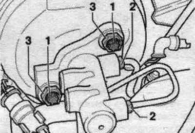
Unscrew bolt "3". Remove retainer "1" on the left side and remove pin "5" by moving it to the right. Remove the brake pedal.
Installation
If possible, do not remove the brake pedal support, as the brake light switch socket may be damaged if the brake pedal is moved abruptly when unlocking. If possible, do not remove the stop "17" from the brake pedal, since the socket of the brake light switch "10" may be damaged if the brake pedal is moved abruptly when unlocking. Slide the retainer onto the finger on the right. Move your finger from right to left along the brake pedal axis. Install retainer "1" on the left pin. The pin should be held by retainers on both sides. Screw in and tighten screw "3." Installing the support bracket on a vehicle with a manual transmission.
Removal and installation the brake pedal on a car with an automatic transmission
Remove the front panel trims from the driver's side "1...3".
Disconnect the air duct wiring. footrest "C". Remove the air duct "A-B". Remove the brake light switch. Disconnect the brake pedal from the brake booster. If possible, do not remove the brake pedal support, as the brake light switch socket may be damaged if the brake pedal is moved abruptly when unlocking.
Unscrew bolt "11". Remove retainer "5" and remove pin "4" by moving it to the left.
Installation
If possible, do not remove the stop "17" from the brake pedal, since the socket of the brake light switch "10" may be damaged if the brake pedal is moved abruptly when unlocking. Slide the "12" lock onto the left finger. Move your finger from left to right along the brake pedal axis. Install retainer "5" on the right pin. The pin should be held by retainers "5" and "12" on both sides. Screw in and tighten screw "11." Install the brake booster rod into the brake pedal socket. Align the ball head with the push rod socket, press the brake pedal towards the brake booster, the ball head will enter and install in the socket with a clearly audible click. Install the brake light switch. Install the air duct for the air vent. for legs "A-B". Tighten the screw of the air duct "A". Connect the wiring of the air duct for blowing space. for feet "C". Install the front panel trims on the driver's side "1...3".
Removal and installation the support bracket, vehicles with manual transmission
Remove the front panel trims from the driver's side "1...3".
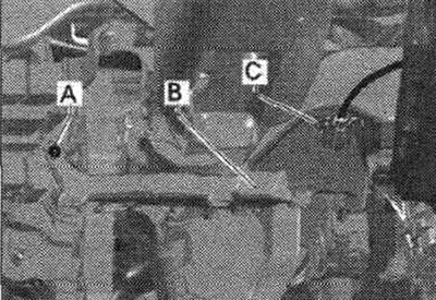
Disconnect the air duct wiring. for legs "C". Remove air duct "A-B".
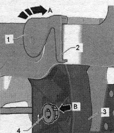
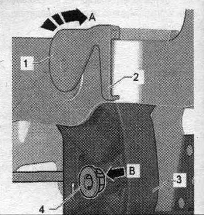
Remove the brake light switch. Disconnect the connector from the gas pedal module. Disconnect the brake pedal from the brake booster. If possible, do not remove the brake pedal support, as the brake light switch socket may be damaged if the brake pedal is moved abruptly when unlocking. Remove servo spring "2" from clutch pedal "1". During subsequent installation, observe the correct installation instructions. servo spring position.
Remove the main cyl. pin. clutch from clutch pedal "4", Locks "1 and 2" can only be unlocked after removal.
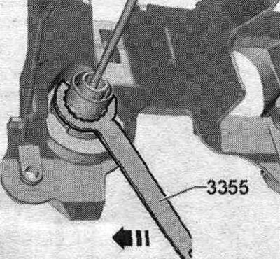
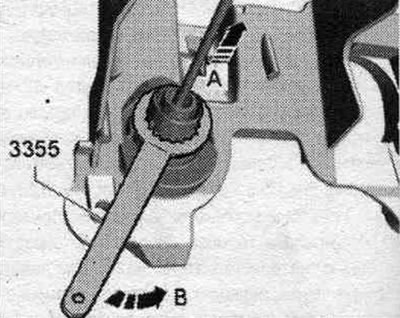
Unlock the clutch master cylinder using the puller "3355". Turn the tool clockwise "arrow".
Remove the stretch. Remove the partition of the water drainage box. Remove cover "2" of the expansion tank.
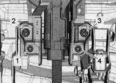
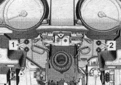
Cover "2" is not installed on all vehicles. Remove screws "1" securing the brake booster to the support bracket.
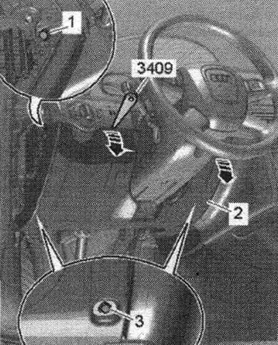
Unscrew the "16" nuts on the support bracket guides. Set the steering wheel as close to the driver's seat as possible. Set the steering wheel to the straight-ahead position. The wheels are straight. Removing the steering column does not require removing the steering wheel or dashboard. Unscrew screw "2" from the bottom of the steering column.
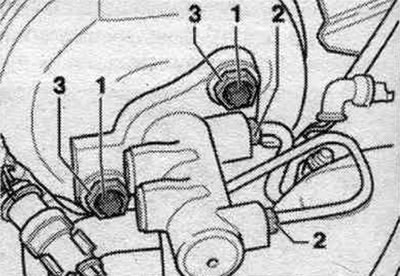
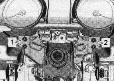
Unscrew screws "2...4" securing the steering column and support bracket.
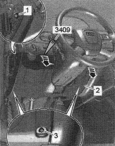
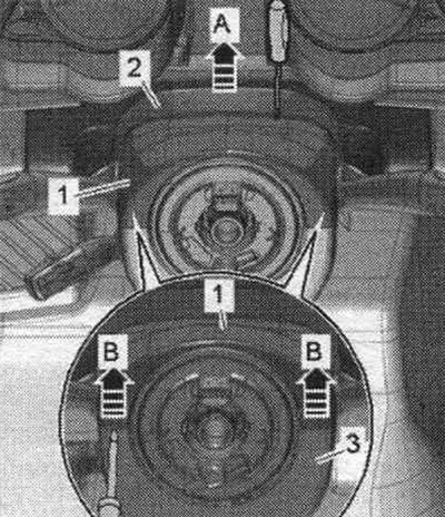
Remove cover "2" from the upper cover "1" of the steering column switch module "arrow A". Hang up the steering column cables. The figure shows an image without a steering wheel. Removal of the steering wheel and dashboard is not required.
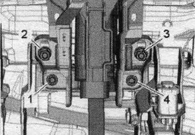
Remove screws "1 and 2" on the steering column frame while holding the steering wheel. column with your hand from below. Loosen and unscrew the screws "1 and 2" using a standard ratchet with a 3/8-inch multi-tooth socket and extension.
Remove the steering wheel. column from the steering shaft. Place the steering wheel carefully. column with a steering wheel. Remove the support bracket from the vehicle. When removing the support bracket, the clutch master cylinder must not be disconnected from the hydraulic lines. The clutch master cylinder remains on the vehicle.
Installation
If possible, do not remove the brake pedal support, as the brake light switch socket may be damaged if the brake pedal is moved abruptly when unlocking. Before installing the support bracket, check the position of the master cylinder gasket. clutch. Install the support bracket into the guides on the vehicle. Insert the clutch master cylinder through the hole in the support bracket, while slightly turning it to the right so that the cylinder mounts. aligned with the support bracket. Tighten the nuts on the guides to secure the support bracket. Tighten screws "1" securing the brake booster to the support bracket. First, tighten the screws that secure the brake booster to the support bracket.
Tighten the "16" nuts on the support bracket guides. Secure the clutch master cylinder using puller "3355". Turn the tool counterclockwise "arrow B" while moving the master cylinder forward "arrow".
Move pin "4" in the clutch pedal toward the master cylinder and insert flush. Check the installation. finger position. The groove of the pin "B" must coincide with the groove of the pedal.
Install servo spring "2" on the clutch pedal. Connect the connector to the accelerator pedal module.
Install the brake booster rod into the brake pedal socket. Align the ball head with the push rod socket, press the brake pedal towards the brake booster, the ball head will enter and install in the socket with a clearly audible click. Install the brake light switch. Insert the steering wheel. column "1" into steering shaft "3". Insert steering. column into the central tubular frame and tighten the screws. Take into account the different lengths of the screws.
Tighten the screws "1 and 2" crosswise to 20 Nm. Tighten the screws "1 and 2" using a standard ratchet with a 3/8-inch multi-tooth socket and extension.
Using a torque wrench and a VAS 5122 ratchet with an extension, tighten the screws to 20 Nm. Install the upper cover of the steering column switch module. Secure the steering column cables. Tighten the steering shaft screws "2" to a torque of 20 Nm. Install and tighten the lower screws "1...4" of the steering column and support bracket to a torque of 20 Nm.
Install the air duct for blowing space. for legs "A-B". Tighten the screw of the air duct "A". Connect the wiring of the air duct for blowing space. for feet "C". Install the front panel trims on the driver's side "1...3". Install the cover "2" of the expansion tank. Casing "2" is not installed on all vehicles. Install a water drain box partition. Install a stretcher.