



Table of contents: Parts and components of brakes… ↓ Removal and installation the front… ↓ Replacing the front brake. fBC-57… ↓ Removal and installation of front.… ↓
Parts and components of brakes front. fBC-57 wheels
Note: Install the entire repair kit. After replacing the brakes. press the brake pedal hard several times to get the pads into their working position. To bleed brakes. use a liquid-resistant container to remove air from the tank.
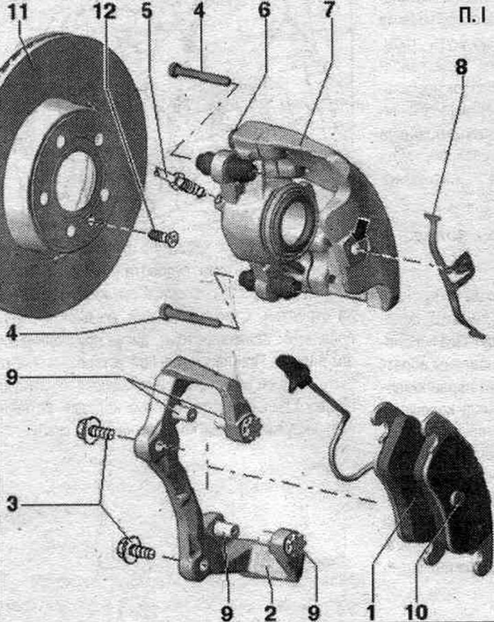
1. Brake pads: Replace all pads for the corresponding axle; before installing the pads, clean the guide surfaces and apply a film of polyurea-based lubricant "G 052 142 A2". Inner pad (with expansion spring) in the left brake. the caliper has a brake wear sensor wire. pads. Before installing new brakes. thoroughly clean the brake pads from any dirt. support (degrease). In this case, special attention should be paid to the cleanliness of the support surfaces and the brake. pads.
2. Brake caliper: attached to the steering knuckle; loosening of brake fastening. brake pads. the bracket is not allowed.
3. Bolt: brake. bracket to steering knuckle; use new screws; 196 Nm.
4. Bolt: brake caliper to bracket; 30 Nm.
5. Brake line to caliper: 20 Nm.
6. Bolt: It is strictly forbidden to loosen the 4 mounting bolts!
7. Brake caliper: when carrying out reinforcement work, do not allow the caliper to hang on the brake. hose, it is necessary to secure the caliper to the body structure elements using wire; the brake caliper is a non-separable unit; no further work on the brake calipers is permitted until the following has been completed: "Brake replacement. pads", "Front brake caliper repair" was not performed and the guide pins were not replaced; when installing the hose, do not allow it to twist.
8. Spring caliper: remove the brake before removing. pads: after installation, install the brake pads. pads.
9. Brake retainer. pads: do not unscrew the brake pad fastening. brake pads. support.
10. Brake disc: replace all pads for the corresponding axle; lubricate the bearing surfaces between the brakes. disc and wheel hub with polyurea grease "G 052 142 A2".
12. Brake disc bolt: 5 Nm.
Removal and installation the front brake. calipers with brakes. fBC-57 bracket
Loosening 4 brake fastening clamps. brake pads. the bracket is not allowed. Raise the car. Remove the wheels. Remove the brake hose from the holder "4".
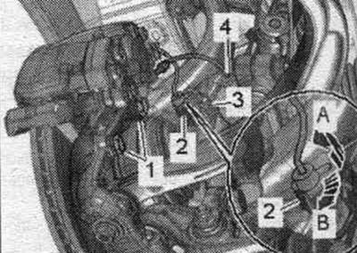
Unlock by moving it to the left and remove the wiring harness from the holder "2-A". Unscrew the screws "1" of the brake caliper. Remove the brake caliper with the pads and brake caliper. caliper. Do not leave brake. caliper with bracket hanging on the brake. hose, use a suitable cable tie or wire to secure it to the body. The brake hose must not be subject to stress. With the brakes released. do not press the brake pedal while holding the caliper.
Installation
Use new screws. Carefully push the brake. caliper with bracket with installed brake pads. disc. Secure the brake. bracket with new screws "1". Insert the brake. hose into bracket "4". Insert wiring harness into holder "2" and secure with rightward movement "B". Install wheels.
Replacing the front brake. fBC-57 calipers
Loosening 4 brake fastening clamps. brake pads. the bracket is not allowed. Install the spacer "VAG 1869/2" between the brake pedal and the driver's seat, so that the pedal is pressed at least 60 mm. In this case, the main brake valves. the cylinders will close and the expansion tank will not be empty. Raise the car. Remove the wheels. Connect the bleeder hose. capacity to the bleed nipple of the front brake. caliper. Open the bleed screw of the front brake caliper. brake pressure relief calipers. syst.. Close the bleed nipple. Spacer "VAG 1869/2" do not remove. Unscrew the brake. pipeline from brake. calipers. Remove the brake pads. Mark the position of the brake pads. pads, if they will still be used. They must be installed in their original locations, otherwise differences in braking performance between wheels may occur! Remove brake caliper "7". Do not loosen bolts "6" and "9"! Remove brake caliper screws "3" while holding the caliper. Remove the brake caliper.
Installation
Use new screws. Install brake. bracket. Secure the brake. bracket with new screws "3". Install the brake. pads. After each replacement of brake pads. press the brake pedal hard several times. This is necessary in order to brake. the pads have taken their working position. Connect and tighten the brake. pipe "5" to the brake caliper. Remove the spacer "VAG 1869/2". Pump up the brakes. syst.. Install wheels.
Removal and installation of front. brake pads FBC-57
Replace all pads for the corresponding axle. Loosening 4 brake fastening clamps. brake pads. the bracket is not allowed. Raise the car. Remove the wheels. Mark the position of the brakes. pads, if they will still be used. They must be installed back in the same places, otherwise uneven distribution of brakes will occur. forces between the wheels! Remove the brake hose from the holder "4". Unlock by moving it to the left and remove the wiring harness from the holder "2" "A". Press the center of the spring latch "8".
Note: The spring is under tension, so do not injure your hands. it is necessary to observe safety precautions.
Carefully remove the spring latch. Disconnect the front left wear sensor connector. The wear sensor is installed only on the inner brake. front left caliper pad. Unscrew and remove both guide bolts "4" from the brake caliper. Do not loosen bolts "6" and "9" under any circumstances! Pull both guide pins slightly to facilitate removal of the brake caliper. caliper. Remove the brake caliper. Do not leave the brake caliper. caliper hanging on the brake. hose, use a suitable cable tie or wire to secure it to the body. The brake hose must not be subject to stress. Remove the brake. pads from the brake housing. calipers and brackets. Loosening 4 brake mounting fasteners. brake pads. the bracket is not allowed.
Installation
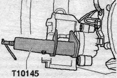
Clean the caliper. Before installing new brakes. press the pistons into the cylinders using a special tool. Before this, pump out the brakes using a special device. liquid from the expansion tank. If the brake fluid was added as the brakes wore out. pads, this will help avoid leaks and the damage they cause. Press the piston into the caliper. To do this, use a tool to press in the brake piston. cyl. T10145.
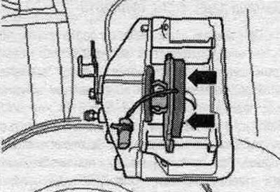
Remove the existing protective film from the back of the brake pads. pads. Insert the inner brake pads. a shoe with a supporting spring in the brake. caliper. The spring latch "arrow" must be in the brake. piston.
Install external brake. shoe "2" into the caliper. Install brake. shoe and press on it so that the fastener enters the hole in the brake. support.
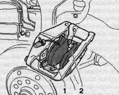
On the brake support plate. the pads have a "10" mount, which should fit securely into the caliper hole. Both brake pads must be held in place by the brake pad retainers. caliper. Two clamps on the brake. the supports on the left and right must not be loose. Carefully push the brake. caliper with brake pads. disc. Screw the brake disc with two guides "4". support to the bracket. Place on the outer brake. spring latch "8". Press the center of the spring latch "8" and insert the middle tongue of the spring latch into the hole "arrow" of the brake caliper. The spring latch tongue must be correctly installed in the hole of the brake caliper. caliper, otherwise the spring may jump out and stop holding the pad. Insert the wear sensor connector into the bracket on the front left. Insert the wiring harness into the holder "2" and secure it by moving it to the right "B". Insert the brake. hose into bracket "4". Connect the wear sensor connector to the front left. Install the front wheels. After installing the brakes. press the brake pedal hard several times to apply the brake pads. This is necessary to ensure that the brakes are applied. the pads have taken their working position.
The original article is available on the website AudiManual.ru