
Table of contents: Electrical parts and components.… ↓ Removal and installation the el.… ↓ Removal and installation of the… ↓
Electrical parts and components. mechan. parking brakes (ERB)
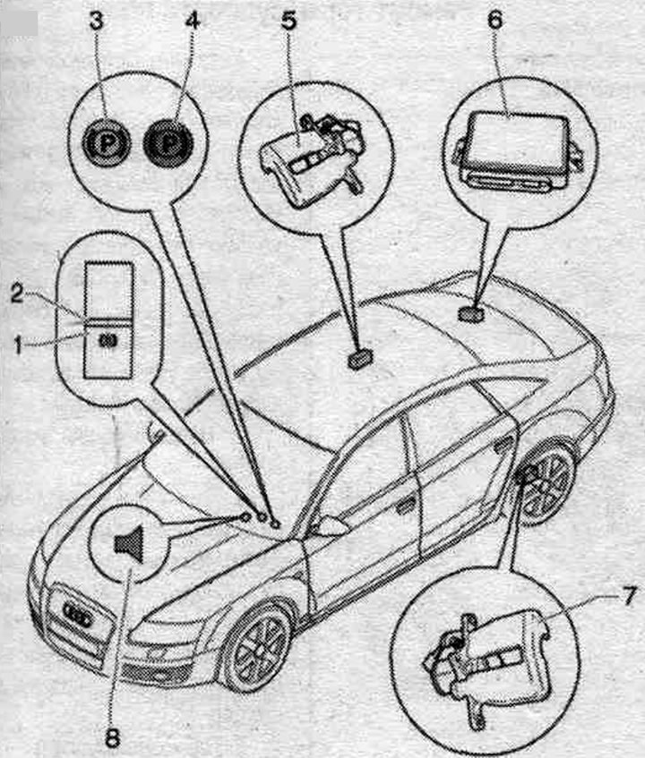
1. Parking switch. "F321" brakes: the switch is illuminated for a long time to make it easier to find in the dark; key pressed — brake engaged "engaged parking. brake"; the key is pressed - the brake is off, to brake you need to press the brake pedal; location: on the center console.
2. LED: installation location: in the parking switch. brakes; lights up when the parking light is on. brake; additional indication is provided by means of a control lamp in the instrument cluster; when slowing down while driving at a speed exceeding 7 km/h, a red segment lights up in the switch and an additional sound signal is emitted.
3. Emergency warning lamp for system malfunction. ERV (yellow): in case of malfunction of the electric system. mechanical parking brake on the display in the instrument cluster add. the yellow symbol lights up and the driver is shown the message: Parkbremse! (Parking brake!).
4. Electrical operation indicator. mechanical parking brake: indicator lights up red: indication of sufficient braking force; with the parking light on. when the brake is applied and the ignition is on, the control lamp lights up; after the ignition is turned off, the control lamp continues to light for approximately 20 seconds if the parking brake is applied and the ignition is on. the brake is applied when the ignition is off, the control lamp lights up and continues to light for approximately 20 seconds after the parking brake is turned off. the brakes should go out and the control lamp should come on; the indicator flashes red: if after turning on the parking. the brake indicator light is constantly red, this may mean the following: the parking brake force. the brakes are not sufficient to prevent the vehicle from rolling, the temperature of the brake mechanisms is too high, and if the red indicator light flashes, other measures must be taken to prevent the vehicle from rolling; the indicator lights up green: the indicator for the start assist (SHA) is on; additional, yellow lamp: in case of malfunction of the electrics. mechanical parking brake on the display in the instrument cluster add. the yellow symbol lights up and the driver is shown the message: Parkbremse! (Parking brake!).
5. Execution electric motor parking. brakes in the right brake. support.
6. Electric control unit. mechanical parking brake "J540": installation location: behind the side trim at the rear right, 9 Nm.
7. Executive electric motor. mechanical parking brake in the left brake. support.
8. Sound signal: warning when turned on while driving at a speed exceeding 7 km/h; warning when a malfunction is detected during system operation.
Removal and installation the el. control unit. mechan. parking J540 brakes
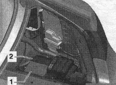
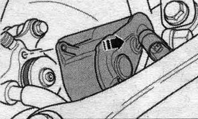
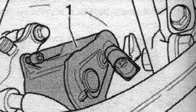
Remove the side trim in the trunk on the right rear. Some models are equipped with a trailer recognition control unit. To remove the el. control unit. mechanical parking brake requires removal of the trailer recognition control unit and its bracket. Loosen the nuts. Move the electrical connector "2" lock forward. Remove the electrical control unit. mechanical parking brake "1" with connected connector. Disconnect the connector from the control unit. Remove the control unit from the car.
Installation
Connect connector "2" to the control unit. Slide back and lock the connector lock. Install the control unit. Tighten the nuts to a torque of 9 Nm. If present, install the trailer recognition control unit and its bracket to a torque of 3 Nm. If the parking brake control unit is being replaced, tighten the nuts to a torque of 9 Nm. brake, then in "Guided fault finding" mode it is necessary to select the "Replace" function for the corresponding control unit. Use the tester "VAS 5051B" or 5052.
Removal and installation of the execution. electric motor el. mechan. parking brakes
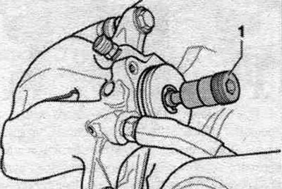
Ignition off. After turning off the ignition, before disconnecting the connector, perform. electric motor, wait at least 30 seconds. Turn off the parking brake. brake. Query the fault memory, correct any detected faults, and clear errors from the fault memory. Raise the vehicle. Remove the wheels. Clean the connector mounting areas and actuators from dirt. electric motor/brake caliper. Disconnect connector "1" of the electric motor.
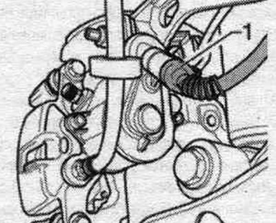
Unscrew both screws securing actuator "1" of the electric motor.
Remove the actuator motor in the direction of the arrow.
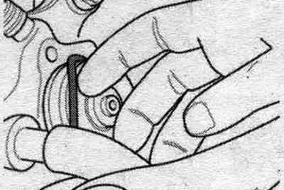
Hold the gasket with a suitable tool. In this case, care must be taken to ensure that the annular groove of the seal is not damaged. rings and mating surfaces executed. electric motor.
Installation
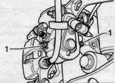
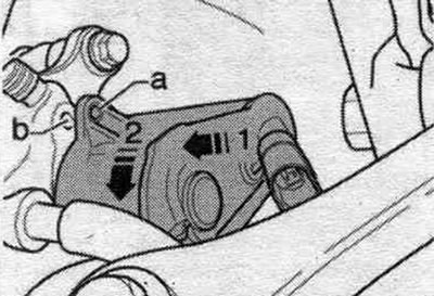
Install a new seal. ring. Loosen the adjusting bolt "1" of the brake caliper a little. This will make installation easier. electric motor.
Install the actuator motor. Ensure that the gasket is positioned correctly. By turning the electric motor, pos. "2", align the hole for bolt "a" with the threaded hole in the brake housing. support "b" and insert the electric motor. In this case, it is necessary to ensure a tight fit of the electric motor to the brake housing. support!
Tighten both mounting screws (Torx 30); electric motor. Bolts execution. tighten the electric motor by hand a few turns. If the threads are damaged, the brake will have to be replaced. the entire caliper! Tighten the screws. electric motor. Tightening torque 12 Nm. Connect the electric wire to the actuator motor. To avoid damaging the connector, only insert it by hand! Do not allow dirt to get inside the connector or damage it.
Insert the motor cable into the bracket. Install the wheels. After replacing the executable. the electric motor should undergo a basic installation of the ERV using a tester (submenu item 006). With the ignition off, connect the tester -VAS 5051B- or "VAS 5052" to the 16-pin diagnostic connector of the vehicle. Ignition on. Turn off the parking brake. brake. Check coding and adjust if necessary. Interrogate the fault memory, eliminate detected faults, erase errors from the fault memory. Select function "053 - Parking brake". Select function "006 - Basic setting", J540 - Electronic control unit. mechanical parking brake, functions, J540 - Basic setting (3 Functional check of el. mechanical parking brake). To exit the input form, press the lower left key with the green arrow.
Checking for leaks by pressing the brake pedal
Turn off the engine. Press the brake pedal until the brake booster stops working, "brake booster empty", the brake pedal is hard. Press the brake pedal 20 mm from the starting position. Maintain pedal pressure for approx. 20 seconds. The pedal stroke should not increase. Release the brake pedal. Press the brake pedal hard. Maintain pedal pressure for approx. 20 seconds. The pedal stroke should not increase. If the pedal fails during any of the checks, repeat the visual check of the brakes. system.. If no leaks are detected during the inspection, there is a high probability of a leak in the main brake. cyl., it needs to be replaced.
[Text provided by the online resource audimanual]