
Table of contents: Brake booster/main brake. cyl. ↓ Removal and installation the brake… ↓ Removal and installation the… ↓ Removal and installation the main… ↓ Removal and installation the brake… ↓ Connecting the brake pedal to the… ↓
Brake booster/main brake. cyl.
Note: Main brake. the cylinder is now manufactured as a non-disassemblable part, in other words, it cannot be repaired.
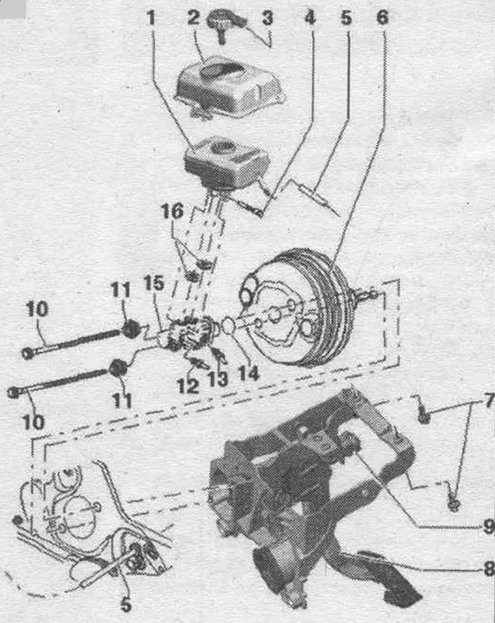
1. Brake reservoir. fluids: Do not remove the mesh filter from the brake fluid reservoir. liquids.
2. Brake reservoir casing. liquids: Not installed on all vehicles. Cover not installed on all vehicles.
3. Tank lid with seal. ring and low brake level sensor. liquids "F34".
4. Bolt: 5 Nm.
5. Pipeline to the main brake. cylinder.
6. Brake booster: check its functionality: with the engine off, press the brake pedal hard several times (this will relieve any residual vacuum in the booster); press the brake pedal with medium force and hold it, start the engine; if the brake booster is working properly, it will require noticeably less force to press the brake pedal (the effect of the amplifier becomes noticeable); with a glued seal, in case of malfunction replace completely.
7. Support bracket screw: 20 Nm.
8. Brake pedal.
9. Brake light switch.
10. Bolt: for attaching the brake booster to the support bracket; 25 Nm.
11. Hexagonal nut of the main brake. cyl.: 49 Nm.
12/13. Brake line: from the main brake. cyl. to hydr. block; 16 Nm.
14. Sealing ring: replace.
15. Main brake. cylinder: cannot be repaired, if faulty, it is replaced entirely.
16. Bushing seal: lubricate the brake. liquid and install the brake fluid reservoir. liquids.
Adjusting the position of the ball head
"a" = 164.7 mm ±0.5 mm.
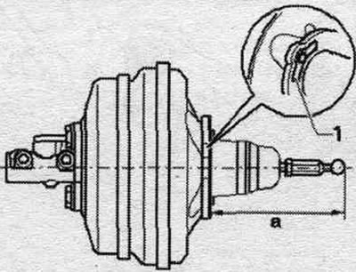
Reference plane "1" for taking measurements. When taking measurements, the ball head must be installed strictly perpendicular to the end surface of the brake booster. Measure the distance from the end of the brake booster to the end of the ball head, not including the thickness of the seal in the measurement. Ball head to rod, 30 Nm.
Removal and installation the brake fluid reservoir casing. liquids
Not installed on all vehicles. There is a hole in the left side of the expansion tank casing for checking the brake fluid level. fluids. To prevent possible damage to the brakes. liquid must not get between the casing and the expansion tank. Remove the water drainage box casing. Unscrew screw "4". Remove the expansion tank casing from the car.
Installation
Install the casing on the expansion tank. Screw in screw plug "4" and tighten it. Install the water drain box casing.
Removal and installation the expansion tank
Remove the water drainage box casing. Disconnect the connector from the brake pressure warning sensor. "F34" liquid. Install the casing on the expansion tank. To prevent leaking brake fluid from entering. place liquids on other parts under the main brake. a sufficient amount of rags that do not leave behind fibers in the cylinder. Bleed as much brake fluid as possible. liquids using the "VAS 5234" device and an adapter "VAS 5234/1" from the expansion tank. On vehicles with a manual transmission, disconnect and plug the clutch line "5" from the expansion tank. Pull the lower retainer out of the expansion tank. Remove the expansion tank from the main brake. cyl..
Installation
Remove the protective cap on the new tank immediately before installation. Lubricate the plugs of the brake fluid expansion tank. liquid. Insert the reservoir into the seals in the main brake. cylinder. Insert the lower retainer of the expansion tank. Connect the low brake pressure warning sensor connector. "F34" fluid. On vehicles with a manual transmission, connect clutch line "5" to the expansion tank. Fill the expansion tank up to the mark. Pump up the brakes. system.. On a car with a manual transmission, bleed the clutch. Install the casing on the expansion tank. Install the water drainage box casing.
Removal and installation the main brake. cyl.
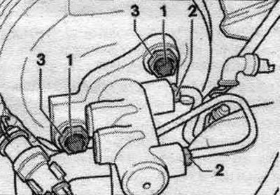
Remove the water drainage box casing. Remove the engine cover. Remove the stretch. Remove the partition of the water drainage box. To prevent leaking brake fluid from entering. place liquids on other parts under the main brake. a sufficient amount of rags that do not leave behind fibers in the cylinder. Bleed as much brake fluid as possible. fluid using a device for filling and bleeding brakes. system "VAS 5234" from the expansion tank. Remove the expansion tank. Unscrew the brake. tubes "2" from the main brake. close the cylinder and brake pipes with plugs from the repair kit. Unscrew the nuts securing the main brake "3". cyl.. Remove the main brake. cylinder from the brake booster. Remove the main brake. cylinder from a car.
Installation
Installation in reverse order. Use only new nuts. Replace the seal. ring between the main brake. cylinder and brake booster. When replacing the main brake. cyl. ensure the correct position of the rod. Press the brake pedal slightly to facilitate the insertion of the piston rod into the main brake. cylinder. Screw in and tighten the new nuts "3". Observe the tightening torque. Connect the brake. pipelines "2" to the main brake. cylinder. Observe the tightening torque. Install expansion tank "1". On vehicles with a manual transmission, connect clutch line "5" to the expansion tank. Fill the expansion tank up to the mark. Pump up the brakes. system.. On a car with a manual transmission, bleed the clutch. Install the partition of the water drainage box. Install a stretcher. Install the engine cover. Install the water drainage box casing. Finally, carry out a system test of the ESP and a test drive.
Removal and installation the brake booster
Turn off the engine. Press the brake pedal until the brake booster stops working, "brake booster empty", the brake pedal is hard. Remove storage compartments from the driver's side "1...3".
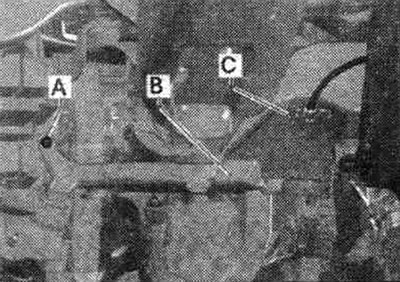
Disconnect the air duct wiring. for feet "C". Remove the air duct "A-B". Remove the brake light switch.
Disconnect the brake pedal from the lava brake booster. Remove the engine cover. Remove the water drainage box casing. Remove the stretch. Remove the partition of the water drainage box. Remove the expansion tank. Remove the main brake. cylinder by unscrewing nuts "3". Remove the main brake. cylinder from the car. Place the main brake. cylinder so that the brake. the liquid did not spill out.
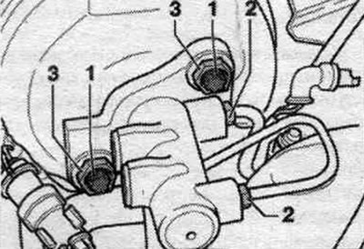
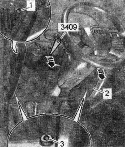
Disconnect vacuum line "3" from the brake booster.
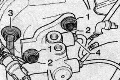
Unscrew screws "1" securing the brake booster to the support bracket. Remove the brake booster from the vehicle.
Installation
Install the brake booster on the car. Check that the gasket is correctly positioned. Tighten screws "1" securing the brake booster to the support bracket. Connect vacuum line "3" to the brake booster. Install the main brake. cylinder "15". Install expansion tank "1". On vehicles with manual transmission, connect clutch line "5" to the expansion tank. Fill the expansion tank up to the mark. Pump up the brakes. system.. On a car with a manual transmission, bleed the clutch. Install the partition of the water drainage box. Install a stretcher. Install the engine cover. Install the water drainage box casing.
Connecting the brake pedal to the brake booster
Align the ball head with the push rod socket, press the brake pedal towards the brake booster. - the ball head will enter and install itself in the socket with a clearly audible click. Install the brake light switch. Install the air duct for the air vent. footrests "A-B". Tighten the air duct screw "A". Connect the connector "C". Install the storage compartments on the driver's side "1...3".
[Text provided by the online resource: Audimanual.ru]