
Table of contents: Removal and installation the V192… ↓ Removal and installation the brake… ↓ Removal and installation the check… ↓ Brake location. pipes/pipelines ↓
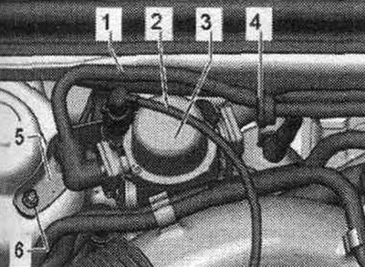
The electric vacuum pump V192 is activated by a signal from the control unit depending on the pressure in the intake manifold.
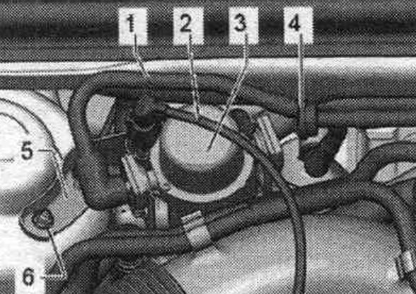
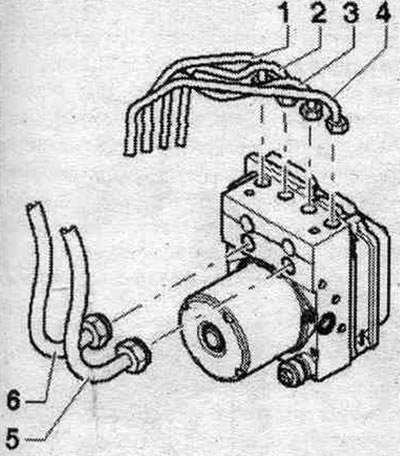
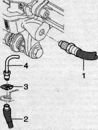
1. Vacuum pipeline.
2. Electrical connector.
3. Brake vacuum pump. syst. "V192".
4. Check valve.
5. Vacuum pump bracket "V192".
6. Bracket nut: 20 Nm.
Removal
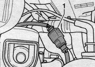
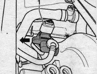
Electric vacuum pump brake vacuum pump. syst. V192 - is activated by a signal from the control unit depending on the pressure in the intake manifold. The vacuum pump cannot be repaired. If any malfunctions occur, their cause should be determined by checking for leaks and functionality. If a fault is detected in the electric vacuum pump, it must be replaced. The electric vacuum pump is located in the engine. compartment on the right side of the partition of the water drainage box. Remove the engine cover. Disconnect connector "1". Remove the vacuum hose clamp using suitable pliers. Disconnect the vacuum hose from the vacuum pump.
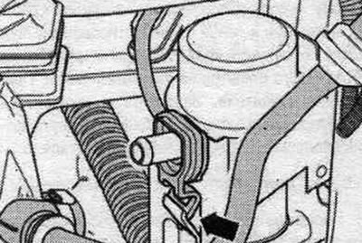
Press the left and right "arrow" fasteners out of the bracket.
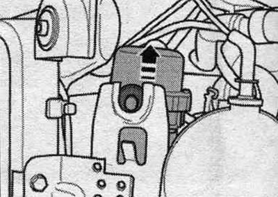
Remove the vacuum pump with an upward movement, while holding the lower rubber stop.
When removing the V192 vacuum pump, do not allow the rubber buffer to fall into the engine. compartment.
Installation
Installation in reverse order. When installing vacuum lines, use new clamps.
Removal and installation the V192 vacuum pump bracket
To remove the bracket, you first need to remove the vacuum pump from it. Remove the engine cover. Remove the vacuum pump. Unscrew 2 nuts "6" on the bracket. Remove the bracket from the car.
Installation in reverse order.
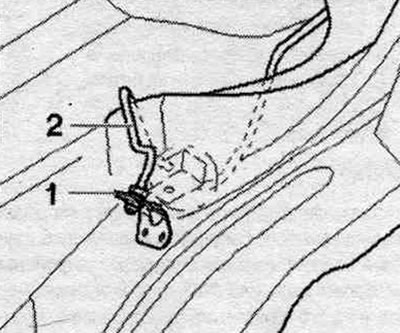
Removal and installation the brake booster pressure sensor "G294"
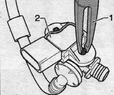
Remove the water drainage box casing. The brake booster pressure sensor "G294" is located in the water drain box next to the brake booster. Disconnect connector "1." Remove the pressure sensor in the direction indicated by the arrow. The pressure sensor is secured with a clamp.
Disconnect the retainer using pliers "1". Carefully pry off the brake booster pressure sensor "G294".
Installation in reverse order.
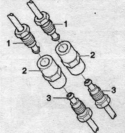
Removal and installation the check valve
Remove the left and right vacuum hoses from check valve "4". Remove the check valve from the vehicle.
Installation
Installation in reverse order. The valve must allow air to flow in the direction of the arrow. The arrow points towards the vacuum pump.
Checking the check valve
The valve must allow air to flow in the direction of the arrow. When air is supplied in the opposite direction, the valve should remain closed and not allow air to pass through. Ensure that the valve is installed correctly. The arrow points towards the vacuum pump.
Brake location. pipes/pipelines
Brake lines and brakes. the tubes are supplied as ready-to-install spare parts. When installing brakes. pipes/pipelines should be secured in the standard locations provided by the design. All pipelines to hydr. block: 14 Nm.
Front axle brake caliper hose
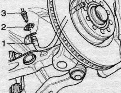
1. Brake hose, check that the clamps are installed correctly in the bracket.
2. Spring latch.
3. Brake line, tightening torque 14 Nm.
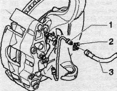
1. Brake line, tightening torque 14 Nm.
2. Spring latch.
3. Brake hose, check that the clamps are installed correctly in the bracket.
Brake location. pipeline in the front wheel arch
1. Brake line, tightening torque 14 Nm.
2. Spacer.
3. Brake line, tightening torque 14 Nm.
Brake connection. pipelines in the front wheel arch
1. Brake bracket. hose.
2. Brake line, tightening torque 14 Nm.
Brake location. pipeline in the back. wheel arch
1. Brake hose to brake. caliper 20 Nm.
2. Brake bracket. hose, check that the clamps are installed correctly in the bracket.
3. Spring latch.
4. Brake line, 14 Nm.