
Table of contents: Brake booster vacuum pumps ↓ Diesel 2.7L/3.0L TDI ↓ Diesel 2.0 l TDI ↓ 4 cyl. turbocharged FSI engine ↓ V6 FSI engine ↓ V6 FSI turbocharged engine ↓
Brake booster vacuum pumps
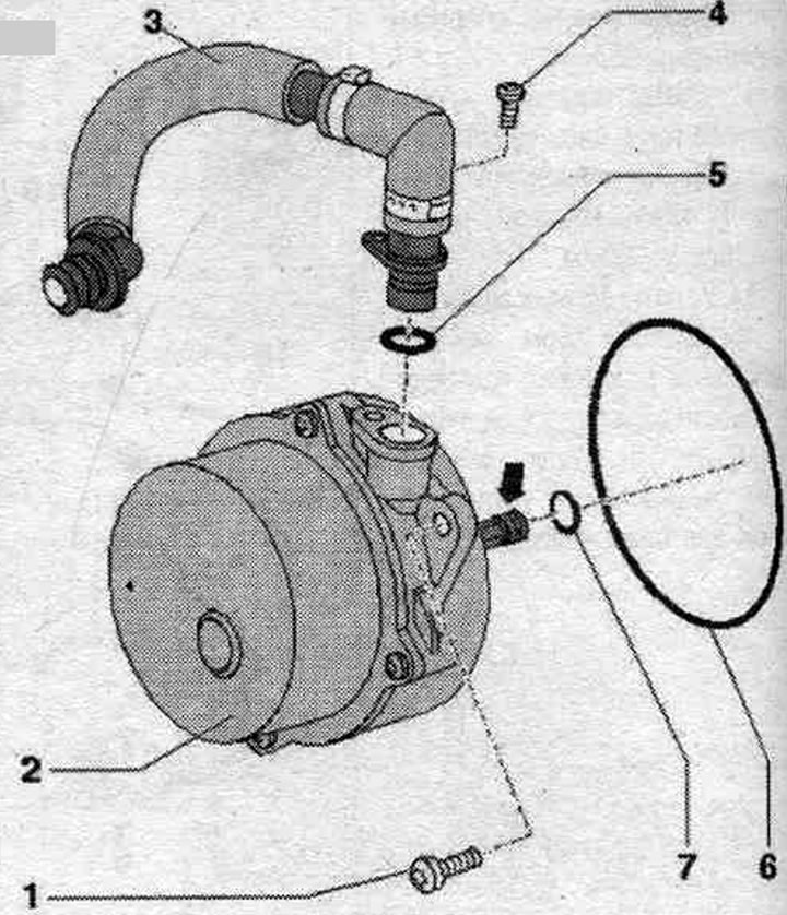
1. Bolt: 9 Nm; to remove, unscrew the pump. Further disassembly of the pump is not provided.
2. Vacuum pump.
3. Vacuum hose: Use clamps of the appropriate series to secure the hoses.
4. Bolt: 5 Nm.
5-7. Sealing ring: replace.
Diesel 2.7L/3.0L TDI
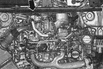
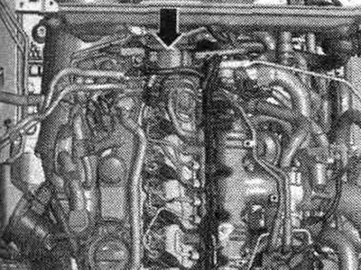
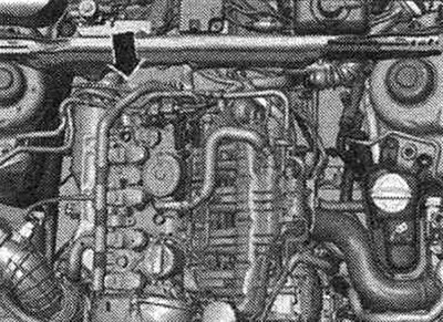
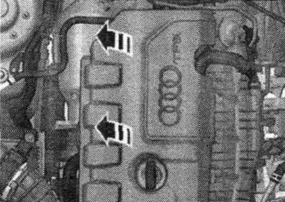
The vacuum pump is installed on the right row of cylinders "arrow" at the rear in the direction of travel.
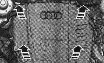
Carefully separate the engine casing from the retainers one by one. To provide more free space. in the engine compartment, disconnect the vacuum tube from the removed vacuum pump and reconnect it when installing the pump.
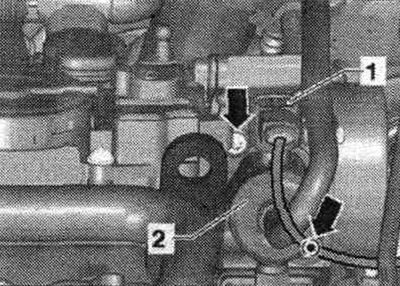
Remove the water drainage box casing. Disconnect the vacuum line and the vacuum hose behind the bulkhead of the water drain box "2".
Remove the water drainage box casing. Disconnect the vacuum line and the vacuum hose behind the bulkhead of the water drain box "2".
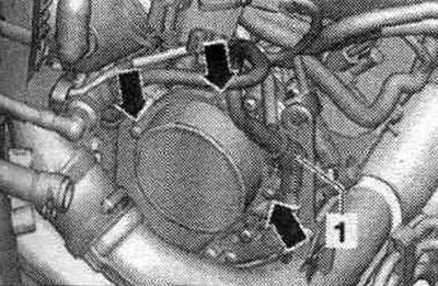
Unscrew all the "arrow" screws on the vacuum pump flange. Remove the vacuum pump from its socket. Remove the vacuum line from the dismantled vacuum pump.
Installation
Replace the gasket. Check that the gasket is positioned correctly during installation. Install the vacuum line onto the removed vacuum pump. Ensure proper installation. position. Turn the vacuum pump drive so that it fits into the camshaft groove when installed. Installing a vacuum pump. Check that the gasket is positioned correctly. Install and tighten all screws on the vacuum pump flange. Insert the vacuum line into the partition of the water drain box. Connect the vacuum line and the vacuum hose behind the bulkhead of the water drain box. Install the water drainage box casing. Install the engine cover.
Diesel 2.0 l TDI
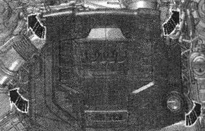
The vacuum pump is located in the engine. compartment at the rear in the direction of travel "arrow".
Remove the engine cover. There is no need to remove the partition of the water drainage box.
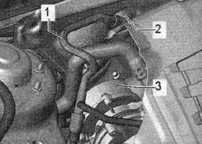
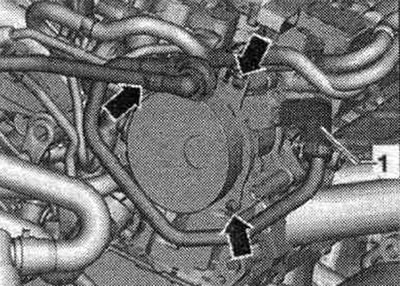
Unscrew the pressure sensor "1" of the diesel particulate filter from the bracket. Unlock the pressure sensor wiring harness "2" and carefully set it aside. Unscrew the pressure sensor bracket from the vacuum pump. Disconnect the coolant hose from the bracket and from the left transport eye and set it aside.
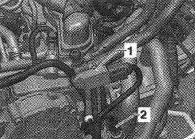
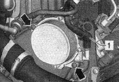
Disconnect vacuum hose "1" from the pump.
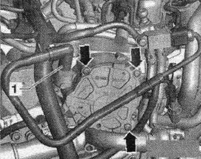
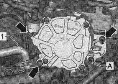
Unscrew all the "arrow" screws on the vacuum pump flange. Remove the vacuum pump from its socket.
Installation
Replace the gasket. Check that the gasket is positioned correctly during installation. Rotate the vacuum pump drive so that it fits into the camshaft groove when installed. Installing a vacuum pump. Check that the gasket is positioned correctly. Screw in and tighten all the "arrow" screws on the vacuum pump flange. Connect the vacuum hose to the vacuum pump. Connect the coolant hose to the bracket and to the left transport eye. Install the bracket for the diesel particulate filter pressure sensor "1" onto the vacuum pump. Screw on the bracket. Secure the pressure sensor wire harnesses to the bracket. Tighten the pressure sensor. Install the engine cover.
4 cyl. turbocharged FSI engine
Before removing the vacuum pump, the high-pressure fuel pump must be removed. Removing the water baffle plate is not necessary. The vacuum pump is located in the engine. compartment at the rear, in the direction of travel, "arrow." The fuel line is under pressure; do not disconnect it at this stage!
Carefully separate the engine covers from the retainers one by one. The vacuum pump is located in the engine. compartment on the right rear in the direction of travel. Unscrew the fuel line bracket from the high-pressure fuel pump.
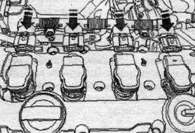
Disconnect connector "1" on the high pressure pump. Disconnect the wiring from the "arrow" bracket. Remove the fuel injection pump "2". Disconnect the coil wiring from the bracket.
Disconnect the "arrow" coil connector. Carefully set the coil wiring aside. Disconnect the fuel injection pump and vacuum pump lines and set them aside. Disconnect the vacuum hose from the vacuum pump clamp.
Unscrew all the "arrow" screws on the vacuum pump flange. Disconnect the vacuum line and the vacuum hose behind the bulkhead of the water drain box "2". Remove the vacuum pump from its socket.
Installation
Replace the gasket. Check that the gasket is positioned correctly during installation. Rotate the vacuum pump drive so that it fits into the camshaft groove when installed. Check that the gasket is positioned correctly. Screw in and tighten all the "arrow" screws on the vacuum pump flange. Install new clamps on the vacuum hose. Place the vacuum hose onto the vacuum pump connection. Tighten the clamps on the vacuum pump hose using suitable pliers. Connect the fuel injection pump and vacuum pump lines. Connect the "arrow" coil connector. Secure the coil wiring. Install the fuel injection pump. Connect the fuel line bracket to the fuel line. high pressure pump. Install the engine cover.
V6 FSI engine
The vacuum pump is located in the engine. compartment in front on the left in the direction of travel. Carefully separate the engine covers from the retainers one by one. Loosen the vacuum hose clamps. Disconnect the vacuum hose from the vacuum pump. Remove all screws on the vacuum pump flange. Remove the vacuum pump from its socket.
Installation
Replace the gasket. Check that the gasket is positioned correctly during installation. Rotate the vacuum pump drive so that it fits into the camshaft groove when installed. Installing a vacuum pump. Check that the gasket is positioned correctly. Install and tighten all screws on the vacuum pump flange. Install new clamps on the vacuum hose. Place the vacuum hose onto the vacuum pump connection. Tighten the clamps on the vacuum pump hose using suitable pliers. Carefully install the engine covers onto the retainers in sequence.
V6 FSI turbocharged engine
The vacuum pump is located in the engine. compartment in front on the left in the direction of travel. Loosen the vacuum hose clamps. Disconnect the vacuum hose from the vacuum pump. Remove all screws on the vacuum pump flange. Remove the vacuum pump from its socket.
Installation
Replace the gasket. Check that the gasket is positioned correctly during installation. Rotate the vacuum pump drive so that it fits into the camshaft groove when installed. Installing a vacuum pump. Check that the gasket is positioned correctly. Install and tighten all screws on the vacuum pump flange. Install new clamps on the vacuum hose.
Place the vacuum hose onto the vacuum pump connection. Tighten the clamps on the vacuum pump hose using suitable pliers.