
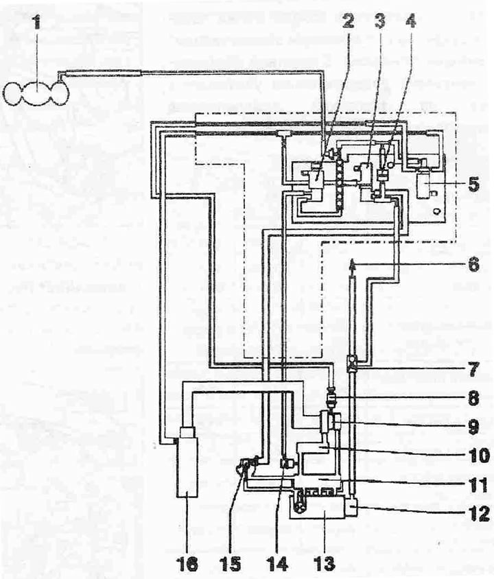
Vacuum hose connection diagram:
1. Vacuum receiver
2. Throttle valve "N₂11"
3. EGR valve "N18"
4. Check valve, white terminal to boost pressure limiting solenoid valve "N75"
5. Boost pressure limitation solenoid valve "N75"
6. To the brake force regulator
7. Check valve
8. Vacuum boost pressure regulator
9. Turbocharger
10. Intercooler
11. Intake manifold
12. Tandem pump for fuel supply and vacuum system supply
13. Cylinder head
14. Vacuum regulator of the intake manifold flap
15. Mechanical valve of the EGR system (component of the air intake pipe, can only be replaced as a complete unit with the air intake pipe)
16. Air filter
Read the original source on the website Audimanual.ru