



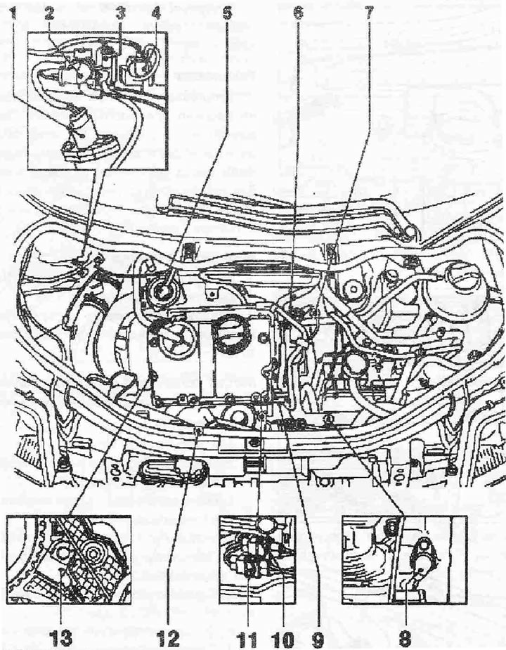
Locations of installation of parts and units on a vehicle with an ANY engine:
Nodes A through H are not shown in the drawing.
1. Air flow meter "G70"
2. Intake manifold flap changeover valve "N₂39"
3. EGR valve "N18"
4. Boost pressure limitation solenoid valve "N75"
5. EGR valve with intake manifold flap
6. Fuel temperature sensor "G81"
7. Coolant temperature sensor "G62"
8. Engine speed sensor "G28"
9. Plug connector of pump-injectors
10. Plug connector of the Hall sensor "G40", for determining the position of the camshaft
11. Plug connector of engine speed sensor "G28"
12. Intake manifold pressure sensor "G71" with intake manifold temperature sensor "G72"
13. Hall sensor "G40" for determining the position of the camshaft
A. Brake pedal sensor "F47" in the footwell on the brake pedal
B. Brake light switch "F" in the footwell on the brake pedal
C. Accelerator pedal position sensor "G79" in the footwell on the accelerator pedal
D. Used direct injection diesel fuel systems "5248". Height sensor "F96"
E. Glow Plug Relay "J52"
F. Power supply relay, cl. 30 "J317"
G. Low power heating relay "J359"
H. High Power Heating Relay "J360"