
Table of contents: Removal and installation the oil pan… ↓ Removal and installation the oil… ↓
Note: If, during repairs, an increased amount of metal shavings or wear products in the engine oil are found in the engine, then to avoid subsequent damage, the lubrication channels should be thoroughly cleaned and the oil cooler should be replaced.
Note: Major repairs are carried out in the same way as for 2.0 TFSI engines (see Section 28).
1. The installation details of the lubrication system components are shown in the illustrations.
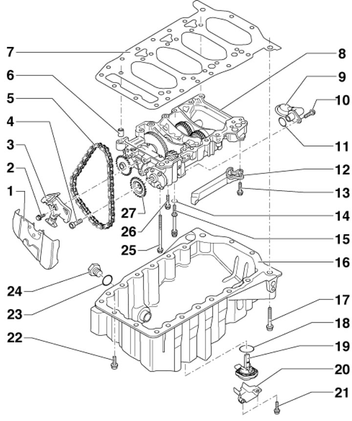
16.1a. Oil pan and balance shaft module with oil pump 1. Chain sprocket cover 5; 2. Tensioner mounting bolt 3, 15 Nm; 3. Chain tensioner 5; 4. Sprocket mounting bolt 27, 20 Nm, then tighten to an angle of 90°, use a new bolt; 5. Oil pump and balance shaft drive chain; 6. Guide bushing; 7. Spacer; 8. Balance shaft module with oil pump; 9. Oil intake with mesh filter; 10. Oil intake mounting bolt 9.9 Nm; 11. Sealing ring, subject to replacement; 12. Oil pipeline; 13. Pipeline fastening bolt 12.9 Nm; 14. Sealing ring, subject to replacement; 15. Module mounting bolt 8, 15 Nm, then tighten to an angle of 15°, use a new bolt; 16. Oil pan; 17. Bolt M10 for fastening the oil pan 16, 15 Nm; 18. Sealing ring, subject to replacement; 19. Oil level and temperature sensor; 20. Sensor housing 19; 21. Casing mounting bolt 20, 10 Nm; 22. Bolt M7 for fastening the oil pan 16, 17 Nm; 23. Plug seal 24, subject to replacement; 24. Oil drain plug, 30 Nm; 25, 26. Module mounting bolts 8, 15 Nm, then tighten to an angle of 15°, use a new bolt; 27. Oil pump sprocket
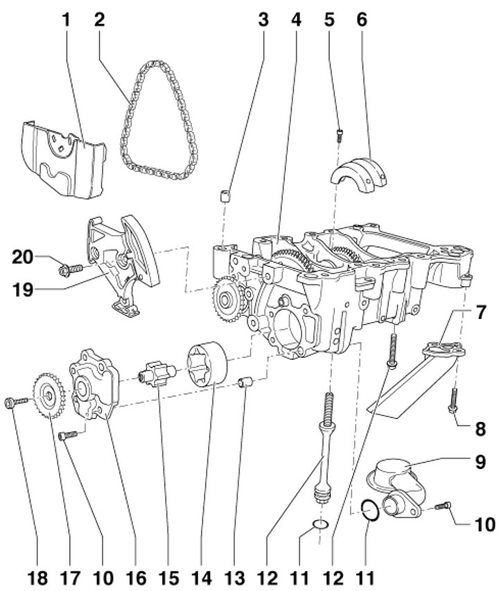
16.1b. Oil pump with balance shaft drive 1. Chain sprocket housing 2; 2. Oil pump and balance shaft drive chain; 3. Centering bushings; 4. Oil pump with balance shaft drive; 5. Cover mounting bolts 6.3 Nm, apply varnish to the threads; 6. Anti-foaming lid; 7. Oil pipeline with lip seal; 8. Pipeline fastening bolt 7.9 Nm; 9. Oil intake with mesh filter; 10. Oil intake mounting bolt, 9 Nm; 11. Sealing ring, subject to replacement; 12. Assembly mounting bolts 4, 15 Nm, then tighten to an angle of 15°, use new bolts; 13. Centering bushings; 14. Outer rotor of oil pump; 15. Inner rotor of oil pump; 16. Oil pump cover; 17. Oil pump sprocket; 18. Sprocket mounting bolt 17, 20 Nm, then tighten to an angle of 90°, use a new bolt; 19. Chain tensioner 2 with tensioner bar; 20. Tensioner mounting bolt 19, 15 Nm
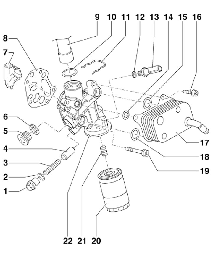
16.1c. Oil filter and oil cooler 1. Threaded plug of the safety valve, 40 Nm; 2. Lip seal, subject to replacement; 3. Safety valve spring (4 bar); 4. Safety valve piston (4 bar); 5. Threaded plug, 15 Nm; 6. Lip seal, subject to replacement; 7. Oil separator; 8. Gasket, subject to replacement; 9. PCV tube; 10. Sealing ring, subject to replacement; 11. Clamp bracket; 12. Lip seal, subject to replacement; 13. Oil pressure sensor with black insulation (at 1.4 bar), 20 Nm; 14, 15. Gasket, subject to replacement; 16. Oil cooler mounting bolt, 15 Nm, then tighten to 90°, use a new bolt; 17. Oil cooler; 18. Gasket, subject to replacement; 19. Bracket mounting bolt 22, 15 Nm, then tighten to an angle of 90°, use a new bolt; 20. Oil filter, 20 Nm; 21. Threaded nipple; 22. Oil filter bracket with safety valve (4 bar)
Removal and installation the oil pan and balance shaft module
Note: When removing the oil pan, the balance shaft module must be removed and the gasket replaced; during installation, reinstall all cable fasteners that were removed or cut during disassembly.
2. Remove the decorative (upper) engine cover upwards (see illustration 5.21).
3. If there is a casing (1 in illustration 5.11) on the right side of the engine compartment, remove this cover.
4. Disconnect the EVAP valve solenoid connector (1 in illustration 5.12) and remove the electromagnetic valve. Unscrew the screws (arrows) and remove the air duct (2).
5. Mark the alternator belt with chalk or a felt-tip pen to indicate the direction of rotation so that you can install the belt in the same way. Loosen the belt tension by turning the tensioner in the direction of the arrow (see illustration), and take it off.
Note: If you cannot remove the alternator belt from the belt pulley, you should unscrew the tensioner mounting bolts a few turns.
6. Remove the engine compartment seal on the connecting edges of the wings. To avoid damaging the connecting edges of the wings, use the No.10-222-A hanging device to place the No. T40045 wing gaskets on both sides between the connecting edges of the wings and the vertical sheet below (see illustration).
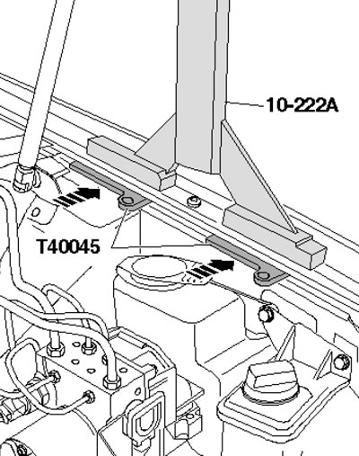
16.6. Preparing to hang the engine
7. Install the crossmember #10-222-A on the connecting edges of the wings with the lead screw backwards. Install the hanging device #10-222 A/12 on the rear engine eyes, install the spindle hook #10-222 A/11 in it and lift the engine using the crossmember lead screw (see illustration).
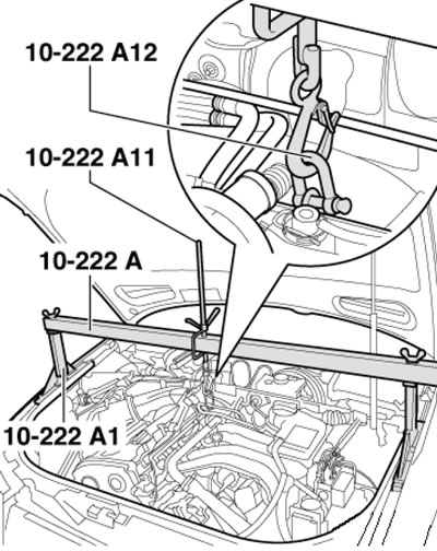
16.7. Hanging the engine
8. On models with independent/additional heating, unscrew the bolts (arrows in illustration 5.4) its exhaust pipe from the soundproofing screen.
9. Unscrew the fasteners (1 and 2 in Illustration 5.5) and remove the front sound insulation screen. Where available, loosen the quick-release couplings (3) and remove the rear sound insulation screen.
10. Unscrew the fastener of the soundproofing screen holder (see illustration 5.6).
11. Pump out the engine oil, disconnect the connector (see illustration 5.47) oil level and temperature sensor.
12. Remove the bolt securing the refrigerant line bracket to the oil pan (see illustration 5.48).
13. Disconnect the connector (1 in illustration 5.49) the wiring of the electromagnetic clutch of the air conditioning system compressor, unscrew the bolts (arrows) securing the compressor to the bracket and hang the compressor on the body without disconnecting the refrigerant lines from it.
14. Remove the bolts (see illustration) and remove the engine jet support.
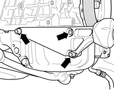
16.14. Fastening of the engine jet support
15. Remove the bolts (1 and 2 in the illustration) and remove the anti-roll bar supports.
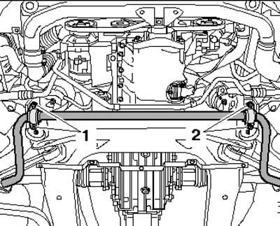
16.15. Fastening the stabilizer supports
16. Cut the starter wiring clamps (see illustration) and remove the wiring. Support the front subframe from below with a transmission jack.
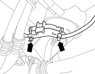
16.16. Starter Wiring Clamps
17. Give the nut (3 in the illustration) at the bottom of the engine mount, remove the bolts (4 and 5) of the engine mount console and the front bolt (1) of the subframe. Remove the engine mount console (2) and repeat this procedure on the other side of the engine.
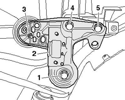
16.17. Engine support console fastening
18. Slowly lower the subframe on the transmission jack. Pull the engine up slightly using spindles #10-222A/11 of the #10-222A lifting device, ensuring that there is free play in the tie rod/shift lever system and the exhaust system (see illustration 16.7).
19. Unscrew the bolt (see illustration) intake manifold supports.
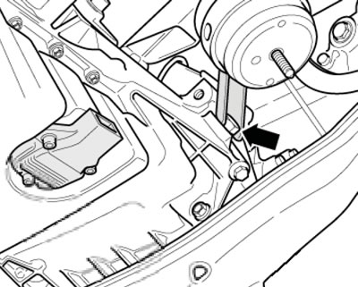
16.19. Intake manifold support bolt
20. Remove the transmission mounting bolts from the oil pan (see illustration 5.52).
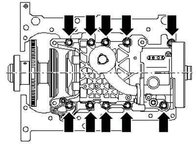
21. Unscrew the M10 bolts (arrows in the illustration), loosen the bolts (1-18) crosswise, unscrew all the bolts and remove the oil pan, lightly tapping it with a rubber-faced hammer if necessary.
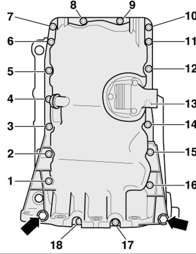
16.21. Oil pan mounting bolts
22. Unscrew the bolts and remove the oil intake (see illustration).
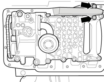
16.22. Oil intake fastener
23. Remove the sprocket cover by carefully pressing the clips in the holes with a screwdriver (see illustration).
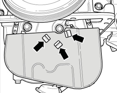
16.23. Sprocket housing retainers
24. Loosen the bolt (4 in illustration 16.1a) fastenings of the oil pump sprocket by approximately one turn. Lower the damper bar down with a screwdriver (arrow on the illustration) and secure the damper bar with a 3 mm rod wrench (1).
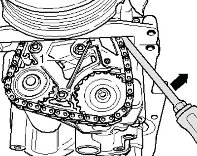
16.24. Fixing the chain guide bar
25. Remove the oil pump sprocket and hang the chain on the balance shaft module. Remove the bolt (see illustration) fastening the balance shaft module in sequence from outside to inside, remove the balance shaft module. The installation process is described below.
16.25. Balance shaft module fastening
26. Prepare the following new parts: oil pan gasket, oil seals, sealing rings and bolts/screws tightened to a certain angle.
27. Remove any remaining sealant from the mating surfaces of the oil pan and cylinder block, clean all seating surfaces from oil and grease.
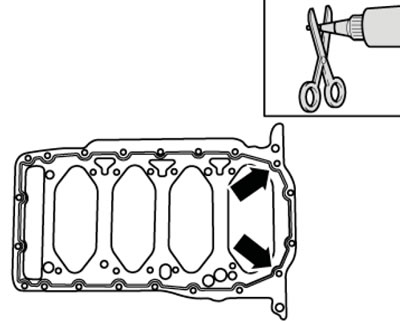
28. Apply a 2-3 mm diameter bead of sealant to the clean surface of the oil pan gasket on the cylinder block side as shown in the illustration.
16.28. Places of sealant application
Note: In the area of the threaded holes, the bead of sealant should run along the inside; in the area of the rear sealing flange (arrows), apply the sealant with particular care. In addition, ensure that the bead of sealant bypasses the oil return channels on the right side of the cylinder block. The balance shaft module and oil pan must be installed within 5 minutes of applying the sealant.
29. Install the gasket on the installation bushings of the balance shaft module with sealant to the cylinder block. Prepare new balance shaft module mounting bolts and a new balance shaft module bolt sealing ring. Install the balance shaft module with the oil pump on the centering bushings.
30. Screw in all the balance shaft module mounting bolts by hand, taking into account the length of the bolts. Moving from the center to the edges, tighten the bolts with a force of 15 Nm, and then tighten them to an angle of 15°.
31. Turn the crankshaft clockwise by the pulley bolt until the marks (see bottom of illustration 10.15).
32. Put a mark (arrow on the illustration) on the balance shaft sprocket opposite the locking hole, fix the sprocket in this position using mandrel No. T10060 or No. T10060A and put the chain on the balance shaft sprocket. Install the oil pump sprocket and tighten its mounting bolt by hand.
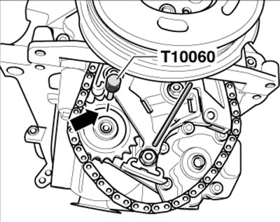
16.32. Installing the oil pump sprocket
Note: The oil pump sprocket can only be installed in one position; during installation, only the oil pump can be turned.
33. Remove mandrel No. T10060 or No. T10060A and rod wrench (1 in illustration 16.24). Tighten the oil pump sprocket bolt to the specified torque and install the sprocket housing (see illustration 16.23).
34. Install the oil line (see illustration 16.22).
35. Install the oil pan and screw in its mounting bolts in the sequence shown in Illustration 16.21:
- a) tighten bolts 1-18 with a force of 5 Nm, alternating crosswise;
- b) tighten the oil pan/transmission bolts to 45 Nm;
- c) tighten the M10 bolts (arrows) to 40 Nm;
- d) tighten bolts 1-18 crosswise to 15 Nm.
36. When installing the oil pan (3 in the illustration) on the removed engine, pay attention to the fact that the pallet should be flush with the intermediate shield (1), i.e. the pallet should protrude beyond the cylinder block (2) by the size (a) - 0.8 mm. After installation, the sealant should dry for about 30 minutes. Only then can you fill in the engine oil.
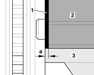
16.36. Installation position of the oil pan
37. Install the subframe and stabilizer (see Chapter 10).
Note: Tighten the engine jet mount to the oil pan and the engine mount to the console to 23 Nm.
38. Install the air conditioning compressor (see Chapter 3).
39. Install the alternator belt (see Section 7), fill the engine oil and adjust its level (see Chapter 1).
Removal and installation the oil cooler and oil filter housing
40. Drain the coolant and remove the upper coolant pipe (see Chapter 3).
41. Remove the intake manifold (see Chapter 4).
42. Remove the lower pipe of the cooling system (see Chapter 3).
43. Remove the bolts (see illustration) and remove the oil cooler.
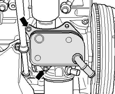
16.43. Oil cooler mounting
44. If necessary, disconnect the connector (1 in the illustration), unscrew the bolts (arrows) and remove the oil filter housing.
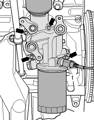
16.44. Removing the oil filter housing
45. Installation is carried out in the reverse order of dismantling the components.
[This article was copied from an online resource audimanual.ru]