
2. The piston and connecting rod installation details are shown in the illustration. The connecting rod bearing caps fit only their connecting rods and only in one position. The connecting rods and their caps are replaced only as a set.
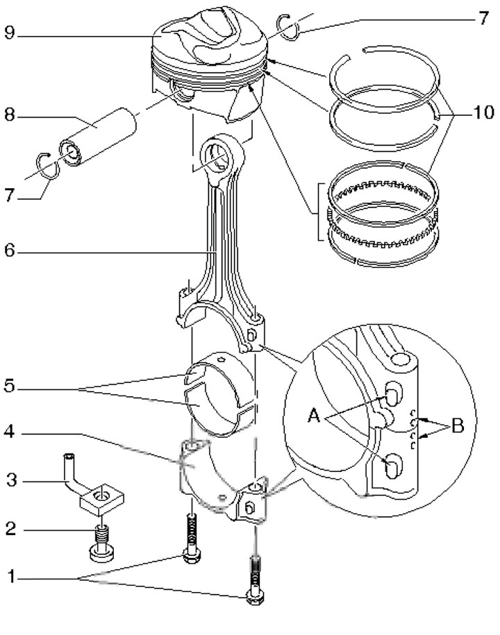
28.2. Piston and connecting rod installation details 1. Cover mounting bolts 4, 30 Nm, then tighten to an angle of 90°, use new bolts; 2. Injector safety valve 3, 27 Nm; 3. Oil nozzle for piston cooling; 4. Connecting rod bearing cap with connecting rod combination mark (B) and front side mark (A); 5. Connecting rod bearing shells (top - with a hole); 6. Connecting rod with marks (see point 4); 7. Pin retaining ring 8; 8. Piston pin; 9. Piston, arrow facing forward (on MPI engines the piston bottom is flat); 10. Piston rings (mark "TOP" facing up)
3. The crankshaft installation details are shown in the illustration.
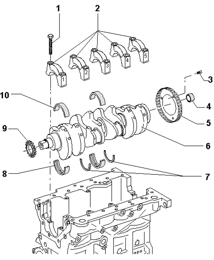
28.3. Crankshaft installation details 1. Cover fastening bolt 2, 65 Nm, then tighten to an angle of 90°, use new bolts; 2. Crankshaft main bearing caps (cover No.3 has recesses for washers 7); 3. Rotor mounting bolts 5, 10 Nm, then tighten to an angle of 90°, use new bolts; 4. Needle bearing (only on models with manual transmission); 5. Rotor of the CKR sensor (after removal it must be replaced); 6. Crankshaft; 7. Adjusting washers for main bearing No.3; 8. Main bearing shell (with a groove) on the cylinder block side; 9. Sprocket for oil pump drive chain, after removal it must be replaced; 10. Main bearing shell (without groove) on the side of the lid
4. Install the main bearing shells on the cylinder block side with the correct color marking, determined by the letter in the corresponding position of the code (see illustration): B - blue, R - red, G - yellow, S - black, W - white.
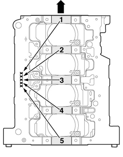
28.4. Color marking code for main bearing shells in the block
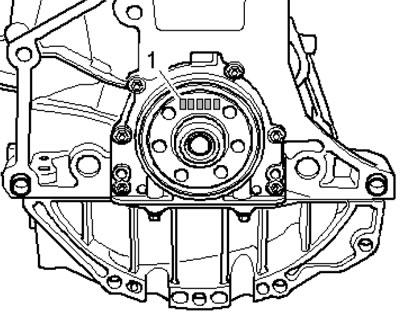
28.4. Color marking code for main bearing shells in caps
5. The main bearing shells installed in the bearing caps for the 2.0 TFSI, 1.6 MPI and 1.8T MPI engines are supplied as spare parts only with yellow colour marking. On 2.0 MPI engines, install the shells with the correct colour marking, determined by the letter in the corresponding position of the code (see illustration): the letter in the far left position (1) indicates the color of the bearing for main journal No.1, and the letter in the far right position indicates the color of the bearing for main journal No.5. The meanings of the letters are the same as for the bearings installed in the cylinder block (see paragraph 4).