
Table of contents: Replacing the exhaust camshaft oil… ↓ Removal and installation the timing… ↓ Removal and installation camshafts ↓
Note: The cylinder head and camshaft cover may only be replaced together. After installing the camshafts, the engine must not be started for approximately 30 minutes (hydraulic compensators must be settled, otherwise the valves will touch the pistons). After working on the valve mechanism, turn the crankshaft by hand at least two revolutions to make sure that no valve is in contact with the piston. The sealing elements must be replaced.
Attention: It is prohibited to modify the intake and exhaust valves; only lapping is allowed.
1. The valve drive mechanism parts are shown in the illustration.
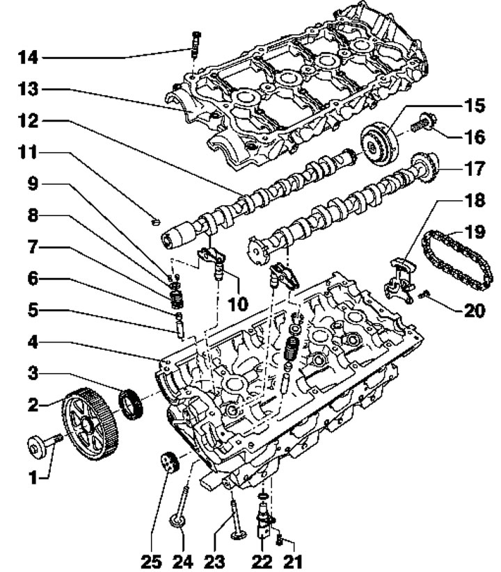
26.1. Valve drive mechanism parts 1. Wheel mounting bolt 2, 50 Nm, then tighten to an angle of 180°; 2. Camshaft gear wheel; 3. Shaft seal 12, subject to replacement; 4. Cylinder head; 5. Valve guide bushing; 6. Oil deflector cap; 7. Valve spring; 8. Upper spring plate 7; 9. Split valve lock crackers; 10. Hydraulic compensator; 11. Prismatic key; 12. Exhaust camshaft; 13. Camshaft cover with built-in bearings (processing is not allowed); 14. Cover mounting bolts 13, 8 Nm, then tighten to an angle of 90°, use new bolts; 15. Sprocket with timing mechanism adjustment; 16. Sprocket mounting bolt 15, 20 Nm, then tighten to an angle of 45°, use a new bolt; 17. Intake camshaft; 18. Chain tensioner 19; 19. Shaft drive chain 17; 20. Tensioner mounting bolt 18, 10 Nm; 21. Sensor mounting bolt 22, 10 Nm; 22. SMR sensor; 23/24. Exhaust/inlet valve; 25. Shaft cover 17, subject to replacement
2. Checking the valve guides is described in Section 15.
3. To remove the cover (25 in illustration 26.1) remove it with an awl, hook it on one side and remove it (with the camshaft cover installed). To install, press the cover without sealant using a suitable mandrel (No. 3334-1) to a depth of 2 mm.
4. To replace the oil-deflecting caps, special devices are used that allow you to squeeze out the valve spring and remove the crackers of the split valve lock (see illustration 26.1). If the procedure is performed with the cylinder head installed, supply compressed air at a pressure of at least 6 bar to the combustion chamber through the spark plug hole.
Replacing the exhaust camshaft oil seal
5. Remove the exhaust camshaft timing gear as described in paragraphs 10-15 of Section 25.
6. Screw the timing gear mounting bolt into the camshaft by hand, unscrew the inner part of the seal puller No.2085 by two turns (by about 3 mm) from the outer part and secure it with a knurled bolt. Lubricate the threaded head of the puller with engine oil, install it and, pressing hard, screw it as deep as possible into the seal (see illustration 14.5). Loosen the knurled bolt and rotate the inner part against the camshaft until the seal is removed. Clamp the flats of the removed puller in a vice and remove the seal with pliers.
7. Place guide sleeve No. T10071/1 on the camshaft journal (see illustration 14.6). Without lubricating the working edge of the seal, put it through the guide sleeve onto the shaft journal, then remove the guide sleeve.
8. Press the oil seal using sleeve No. T10071/3 and bolt No. T10071/4 until it stops (see illustration 14.7).
9. Install the camshaft gear so that the edge of the gear faces outward (arrows in illustration 14.8), and the TDC mark of cylinder No.1 was visible.
10. While holding the gear wheel from turning, tighten its mounting bolt.
Caution: When turning the camshaft with the timing belt removed, none of the pistons should be at TDC.
11. Install the timing belt (see Section 22).
12. Further installation is carried out in the reverse order of dismantling the components.
Removal and installation the timing phase adjustment mechanism
13. Remove the fuel injection pump (see Chapter 4).
14. Remove the two upper timing belt upper cover mounting bolts (see illustration 22.12).
15. Remove the cylinder head cover (see Section 25) and vacuum pump (9 in illustration 25.1).
16. Remove the bolts (see illustration) and remove the timing phase adjustment mechanism housing.
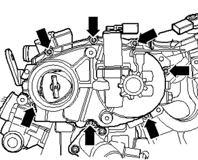
26.16. Fastening the housing of the timing phase adjustment mechanism
17. Align the mark on the camshaft gear with the mark on the timing belt guard. Notches (arrows in illustration 25.25) must stand vertically opposite each other.
18. Install camshaft locking tool No. T10252 as shown in the illustration and secure it (arrows in the illustration). Remove the bolt (15 in illustration 26.1) fastening the timing mechanism with end cap No. T40080.
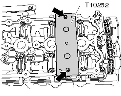
26.18. Camshaft locking tool
19. Compress the chain tensioner (And in the illustration) and install its retainer No. T 10115 (B). Unscrew the fastening bolt of the timing phase adjustment mechanism and remove it together with the chain.
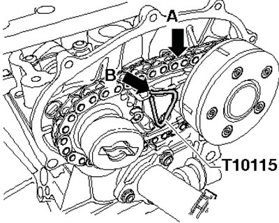
26.19. Fixing the chain tensioner
20. If the chain was removed from the timing mechanism, install the chain.
21. Install the timing mechanism in front of the exhaust shaft to align the cutout (And in the illustration) with a spike (B). In this position, first place the chain on top of the intake camshaft sprocket.
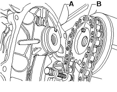
26.21. Installation position of the timing phase adjustment mechanism
22. Slowly turn the intake shaft with key No. T10020 in the direction of the arrow (And in the illustration), until the timing mechanism fits onto the shaft.
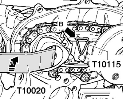
26.22. Installing the timing phase adjustment mechanism
Note: If the pin does not fit into the cutout, remove and reinstall the chain. Tighten the timing chain adjuster mounting bolt.
23. Remove retainer No. T10115 (In the illustration 26.19). Further installation is carried out in the reverse order of dismantling the components.
Removal and installation camshafts
Note: The lower surface of the camshaft cover and the upper surface of the cylinder head must not be treated. After removing the camshaft cover, the exhaust shaft seal and intake shaft cover must be replaced.
24. Remove the cylinder head cover (see Section 25).
25. Remove the timing phase adjustment mechanism (see subsection above).
26. Remove the timing belt (see Section 22).
27. Remove the exhaust camshaft timing gear as described in paragraphs 14-15 Section 25.
26. Remove the bolts securing the rear part of the timing belt protective cover (6 in illustration 22.1).
27. Unscrew the camshaft cover mounting bolts from the edges to the center and remove the cover.
28. Carefully remove the camshafts and place them on a clean surface.
29. Remove old sealant from the camshaft cover groove and from the sealing surfaces. Do not allow dirt or sealant residue to enter the cylinder head.
30. Make sure that the sealing surfaces are free of oil and grease.
31. Make sure the pistons are not at TDC and all rocker arms are properly seated on the valve stem ends.
32. Lubricate the working surfaces of the camshafts with engine oil.
33. Carefully insert the camshafts into the bearings on the cylinder head. Cams (And in the illustration 25.25) 4th cylinders must be facing each other.
34. Apply an even, slightly raised bead of sealant into the clean camshaft cover groove as shown in the illustration.
Note: Do not apply too thick a layer of sealant.
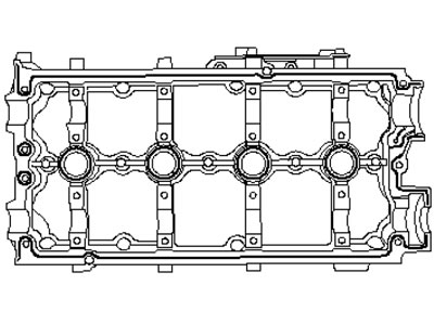
26.34. Places of sealant application
35. Install the camshaft cover so as not to touch the EGR valve (arrow on the illustration).
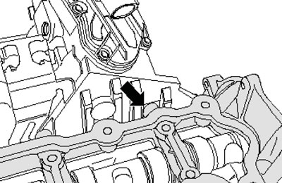
26.35. EGR valve
36. Screw in the new camshaft cover mounting bolts in several stages by hand, and then tighten the bolts to the required torque in the sequence shown in the illustration.
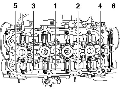
26.36. Sequence of tightening the camshaft cover fasteners
37. Press in a new intake camshaft cover and install a new exhaust camshaft oil seal (see subsection above).
38. Install the rear section of the timing belt cover and insert the key into the camshaft.
39. Install the camshaft gear, timing belt, timing phase adjustment mechanism and cylinder head cover.
40. Further installation is carried out in the reverse order of dismantling the components.
[Material republished from the website: Audimanual.ru]