



Caution! Risk of damage to valves and piston crowns after working on the valve train. Since the hydraulic valve lifters must be settled, do not start the engine for approx. 30 min after installing the camshafts. To ensure that no valve comes into contact with the cylinder head during operation, carefully turn the engine over at least 2 revolutions. Cylinder heads with cracks between the valve seats or between the valve seat ring and the spark plug seat thread can be used without reducing the service life if the cracks are small and have a maximum width of 0.3 mm or if only the first 4 thread turns of the spark plug seat are affected. The illustration shows the cylinder head of cylinder bank 2 (left).
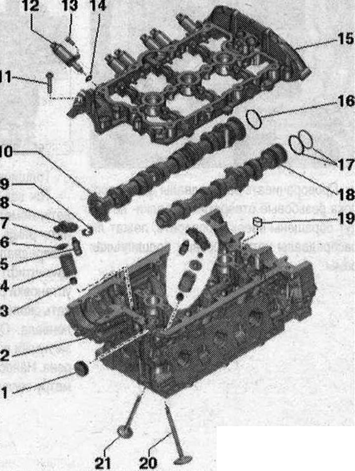
Valve mechanism repair 1. Plug. Install with sealant; 2. Cylinder head; 3. Valve stem seal; 4. Valve spring; 5. Hydrocompensator. Check. Mark the mounting position with paint for reinstallation. Lubricate the working surfaces before installation; 6. Valve spring plate; 7. Valve cracker; 8. Roller lever. Different designs for the intake and exhaust sides, do not confuse! Check the roller bearings for ease of rotation. Lubricate the working surfaces before installation. Secure with the safety clip "pos. 9" on the hydraulic compensator "pos. 5"; 9. Locking bracket. Different designs for the intake and exhaust sides, do not confuse! Check the reliability of the fastening; 10. Intake camshaft with 3 sliders. Do not disassemble. Check radial runout using Plastigage measuring strips (roller levers removed). Radial clearance of bearings 0 24 mm: 0.024...0.066 mm. Radial clearance of bearings O 36 mm: 0.032...0.078 mm. Maximum runout: 0.04 mm; 11. Bolt. Replace; 12. Phase shifter actuator; 13. Bolt, 5 Nm; 14. Sealing ring. Replace; 15. Camshaft frame with integrated camshaft bearings; 16/17. Rectangular section ring; 18. Exhaust camshaft. Checking radial runout using Plastigage measuring strips (roller levers removed). Radial clearance of bearings with a diameter of 24 mm: 0.024...0.066 mm. Radial clearance of bearings with a diameter of 36 mm: 0.032...0.078 mm. Maximum runout: 0.04 mm; 19. Mesh oil filter; 20. Inlet valve. Not subject to machining, only lapping is allowed. Mark the installation position for reinstallation; 21. Exhaust valve. Not subject to machining, only lapping is allowed. Mark the installation position for reinstallation
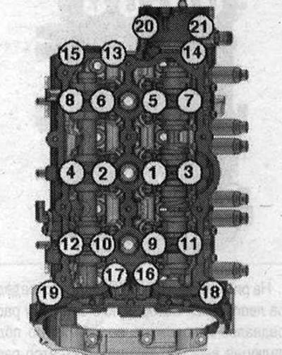
Camshaft Frame. Tightening Sequence and Torque
The figure shows the camshaft frame of the left cylinder head. Replace the camshaft frame mounting bolts. Tighten bolts "1...21" in 3 steps:
- 1. Screw the bolts in until they stop by hand. The frame should fit snugly against the cylinder head over the entire mating surface
- 2. Tighten to 8 Nm
- 3. Turn 90° further
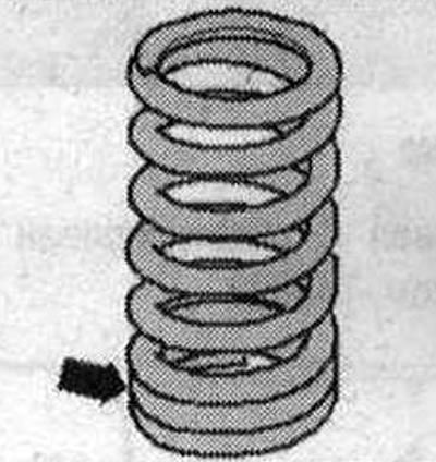
Valve spring installation position
The frequent turns of the "arrow" spring face the cylinder head.
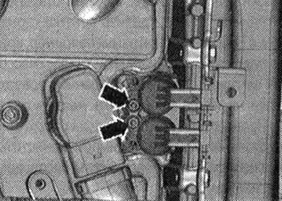
Removal camshafts
Remove the chains from the camshafts. To remove the camshafts from the left cylinder head, remove the brake booster vacuum pump. To remove the camshafts from the right cylinder head, remove the high-pressure pump and the high-pressure pump drive housing. Unscrew the "arrow" bolts and remove the valves of the timing phase control system.
Loosen the camshaft frame bolts in sequence
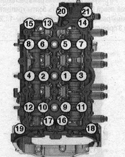
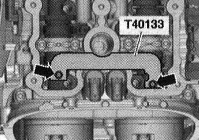
The picture shows the left cylinder head camshaft frame. Carefully remove the camshaft frame and place it on a soft pad on the workbench. Remove the camshaft locking tool "T40133". Mark and remove the camshafts.
Installation
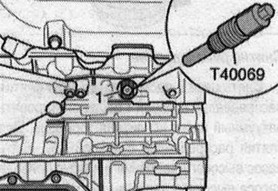
Crankshaft "1" is fixed with fixing bolt "T40069".
Replace all gaskets and seals. Risk of contamination of the lubrication system and bearings. Cover open engine parts. Remove sealant residues from the cylinder head and support frame, for example with a rotating brush attachment with plastic bristles. Clean the mounting surfaces; there should be no oil or grease on them. Check the "arrow" mesh for contamination, clean it if necessary. Lubricate the working surface of the camshafts with oil.
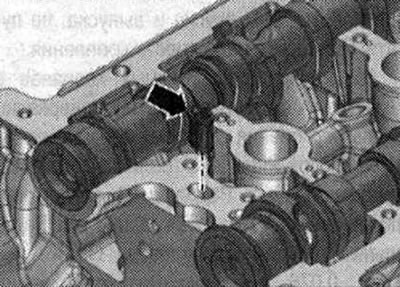
Insert the camshafts into the frame. The camshafts must lie precisely in the axial bearings of the frame "arrows".
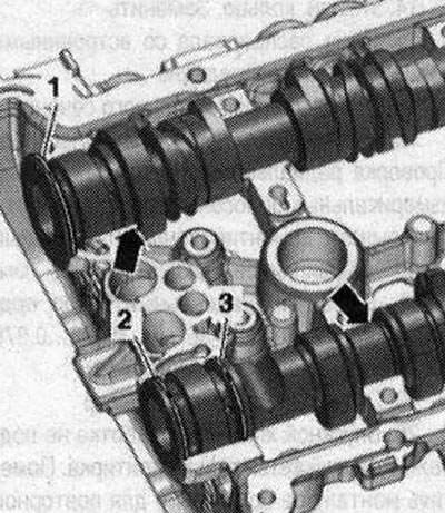
The joints of the rectangular rings "1, 2, 3" must be facing up or down, but never sideways. Rotate the camshaft frame with the camshafts inserted, while holding the camshafts in the frame.
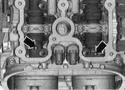
Turn the camshafts until the threaded holes "arrows" are facing upwards. Check whether the camshafts lie precisely in the axial bearings of the frame.
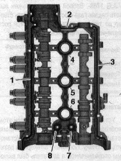
Install the "T40133" camshaft locks on both cylinder heads and tighten the "arrow" bolts to 25 Nm. Take into account the expiration date of the sealant. Cut off the tube tip at the front mark (hole diameter approx. 2.0 mm). Turn the camshaft frame again. Risk of blocking the lubrication system channels if there is too much sealant. The sealant beads must not be thicker than the prescribed size. Apply sealant beads "4...8" to the camshaft frame mounting surfaces as shown in the figure. Sealant bead thickness: 2.0 mm. Apply sealant beads "1...3" to the camshaft frame mounting surfaces as shown in the figure.
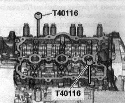
Thickness of the sealant bundle: 2.5 mm.
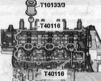
Since the sealant begins to harden immediately, install and secure the camshaft frame immediately. Place the camshaft frame on the cylinder head. Insert the "T40116" locking pins into the frame and cylinder head. After installing the frame, the sealant should harden for about 30 minutes. Tighten the crankshaft frame bolts. Clean the hole for the sealing plug in the cylinder head; it must be degreased. Apply sealant along the outer perimeter of the "arrow" plug.
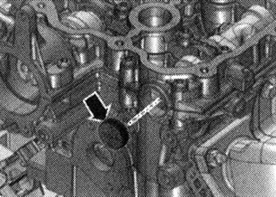
Install the plug flush. Remove the locking pins "T40116" with a slide hammer "T10133/3".
Installation in reverse order: Install the camshaft adjustment valves. Install the brake booster vacuum pump. Install the high-pressure pump and the high-pressure pump drive housing. Install the drive chains on the camshafts. Risk of damage to the valves and piston crowns after working on the valve mechanism. Since the hydraulic valve lifters must be settled, do not start the engine for approx. 30 min after installing the camshafts. To ensure that no valve comes into contact with the cylinder head during operation, carefully turn the engine at least 2 revolutions.