
Attention. Risk of burns from hot steam and hot coolant. When the engine is warm, the cooling system is under excess pressure. To relieve excess pressure, cover the expansion cap. coolant reservoir with a rag and carefully open it. Secure all hose connections with hose clamps of the appropriate series. The arrows marked on the ends of the tubes and hoses of the cooling system must be opposite each other.
Coolant hose connection diagram
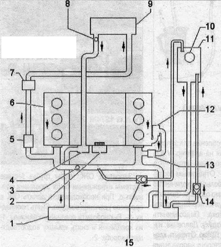
Vehicles without auxiliary heater The arrows show the direction of coolant flow. 1. Radiator. After replacement, change the coolant; 2. Coolant pump; 3. Coolant temperature sensor -G62-; 4. Thermostat; 5. Coolant circulation pump -V50-. Controlled by circulation pump relay -J160-; 6. Cylinder head and cylinder block. After replacement, change the coolant; 7. Coolant shut-off valve. It is controlled via the Climatronic coolant shut-off valve -N422-. The Climatronic coolant shut-off valve -N422- is controlled by a used Climatronic -J255-; 8. Ventilation hole; 9. Heater heat exchanger. After replacement, change the coolant; 10. Extension cover tank; 11. Expansion tank; 12. Oil cooler. After replacement, change the coolant; 13. Coolant circulation pump after engine shutdown -V51- (only on vehicles for use in hot countries); 14/15. Check valve
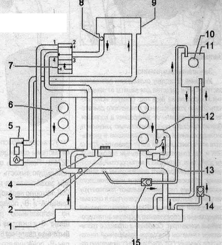
Vehicles with auxiliary heater 1. Radiator. After replacement, change the coolant; 2. Coolant pump; 3. Coolant temperature sensor -G62-; 4. Thermostat; 5. Autonomous heater with circulation pump -V55-; 6. Cylinder head and cylinder block. After replacement, change the coolant; 7. Climatronic coolant shut-off valve -N422-; 8. Ventilation hole; 9. Heater heat exchanger. After replacement, change the coolant; 10. Extension cover tank. Checking the pressure relief valve; 11. Expansion tank; 12. Oil cooler. After replacement, change the coolant; 13. Coolant pump. After switching off the engine -V51- (only on vehicles for use in hot countries); 14/15. Check valve
Visitor comments