
Table of contents: Injection system ↓ Installation location of the engine… ↓ Used fuel pump "J538" "3" ↓ Accelerator Pedal Position Sensor… ↓ Clutch pedal position sensor "G476"… ↓ Oil pressure regulating valve "N428" ↓ Oil pressure sensor for low pressure… ↓ Oil pressure sensor "F22" - arrow ↓ Installation location of the engine… ↓
Installation location diagram
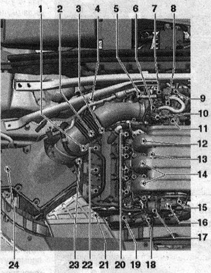
Right side of the engine compartment 1. Lambda probe "G39". 55 Nm; 2. Valve 1 of the variable valve timing system of the exhaust valves "N318". Replace the sealing ring. 2.5 N·m; 3. Valve 1 of the timing phase adjustment "N₂05". Replace the sealing ring. 2.5 N·m; 4. Lambda probe after the catalyst "G130". 55 Nm; 5. Plug connectors of injection nozzles of the cylinder bank of the throttle control unit "J338", knock sensor 1 "G61", lambda probe "G39", lambda probe after the catalytic converter "G130"; 6. Used throttle valve "J338" with electric throttle drive of the electronic gas drive "G186", position sensor 1 of the electric throttle drive of the electronic gas pedal "G187" and position sensor 2 of the electric throttle drive of the electronic gas drive "G188". After replacement, adapt in the "Guided functions" mode with the command "Configure the throttle control unit"; 7. Electromagnetic valve 1 container with activated carbon "N80"; 8. Intake air temperature sensor "C42-/sensor" pressure in the intake manifold "G71"; 9. Secondary air supply control valve "N112" (installed only in vehicles with ULEV 2 emission standards); 10. Secondary air supply control valve 2 "N320" (installed only in vehicles with ULEV 2 emission standards); 11. Coolant shut-off valve Climatronic "N422" (installed only in cars without parking heater); 12. Injector of cylinder bank 1. Injector of cylinder 3 "N32"; 13. Knock sensor 1 "G61"; 14. Injection nozzles. Injector cylinder 1 "N30"; Injector cylinder 2 "N31"; 15. Variable geometry intake manifold position sensor "G513"; 16. Intake manifold sequential changeover valve "N156"; 17. Intake manifold air damper control element; 18. Coolant temperature sensor "G62"; 19. Hall sensor "G40". Replace the sealing ring. 9 N·m; 20. Actuating elements of camshaft phase regulation. Actuating element 1 of camshaft phase regulation "F366"; Actuator element 2 for adjusting the timing phases "F367"; Actuator element 3 for adjusting the timing phases "F368"; Actuator element 4 for adjusting the timing phases "F369"; Executive element 5 of the timing phase regulation "F370"; Executive element 6 of the timing phase regulation "F371"; 21. High pressure pump with low fuel pressure sensor "G410" and fuel metering valve "N₂90"; 22. Ignition coils. Ignition coil 1 with output stage "N70"; Ignition coil 2 with output stage "N127"; Ignition coil 3 with output stage "N₂91"; 23. Hall sensor 3 "G300". Replace the sealing ring. 9 N·m; 24. Electric motor of the secondary air pump "V101" (installed only in vehicles with EU 2 emission standards)
Injection system
Technical specifications
| Idle speed. Not adjustable, adjustment: carried out by means of idle speed stabilizer | 650 - 750 rpm 1) |
| Fuel pressure at the outlet of the high pressure pump | 40 - 10 bar excess pressure |
| Fuel pressure before high pressure pump | 3.0 - 5.7 bar excess pressure |
1) Depending on the requirements for the engine control unit.
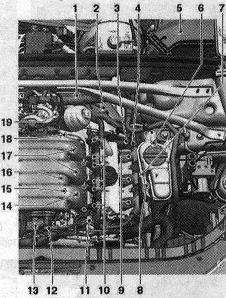
Left side of the engine compartment 1. Left bracket for knock sensor connectors 2 "G66"; injection nozzles of cylinder bank 2; fuel pressure sensor "G247"; lambda probe 2 after catalytic converter "G131"; for lambda probe 2 "G108"; 2. Lambda probe 2 after catalytic converter "G131", 55 Nm; 3. Valve 2 of the timing phase adjustment "N₂08". Replace the sealing ring. 2.5 N·m; 4. Valve 2 of the variable valve timing system of the exhaust valves "N319". Replace the sealing ring. 2.5 N·m; 5. Used engine "J623"; 6. Lambda probe 2 "G108". 55 Nm; 7. Hall sensor 4 "G301". Replace the sealing ring. 9 N·m; 8. Oil pressure regulating valve "N428"; 9. Ignition coils, cylinder bank 2. Ignition coil 4 with output stage "N₂92"; Ignition coil 5 with output stage "N323"; Ignition coil 6 with output stage "N324"; 10. Actuating elements of camshaft phase regulation. Actuating element 7 of camshaft phase regulation "F372"; Actuator element 8 of the timing phase regulation "F373"; Executive element 9 of the timing phase regulation "F374"; Executive element 10 for adjusting the timing phases "F375"; Executive element 11 for adjusting the timing phases "F376"; Executive element 12 for adjusting the timing phases "F377"; 11. Hall sensor 2 "G163". Replace the sealing ring. 9 N·m; 12. Variable geometry intake manifold position sensor "G513"; 13. Intake manifold register switching valve "N156"; 14. Injector of cylinder bank 2. Injector of cylinder 4 "N33"; 15. Fuel pressure sensor "G247"; 16. Knock sensor 2 "G66"; 17. Injectors, cylinder bank 2. Injector cylinder 5 "N83"; Injector cylinder 6 "N84"; 18. Oil pressure sensor for low pressure "F378"; 19. Oil pressure sensor "F22"; A. Engine speed sensor "G28". 9 Nm; B. Used fuel pump "J538". Installed under the right rear seat; C. Accelerator pedal position sensor "G79" / Accelerator pedal position sensor 2 "G185". In the footwell on the accelerator pedal (both sensors are located in one housing); D. Brake light switch "F" and Brake pedal switch "F47" in the footwell on the brake pedal; E. Clutch pedal position sensor "G476" (installed only on vehicles with manual transmission); G. Relay and fuse holder in the electronic unit in the left water drain box
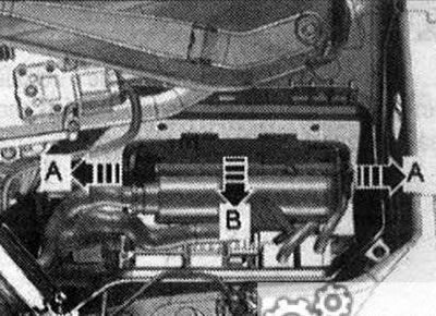
Installation location of the engine control unit "J623"
In the left switching unit of the engine compartment.
Used fuel pump "J538" "3"
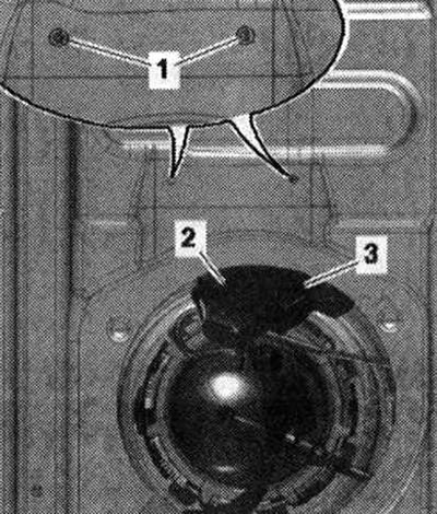
Accelerator Pedal Position Sensor "G79" and Accelerator Pedal Position Sensor 2 "G185"
2. Electrical connector
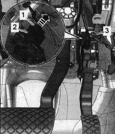
Clutch pedal position sensor "G476" "2"
Built-in functions: Clutch pedal position sensor for engine start "F194" and clutch pedal position sensor "F36"
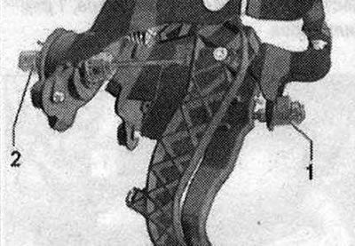
1. Brake light switch "F" and Brake pedal position sensor "F47" (installed only on vehicles with manual transmission)
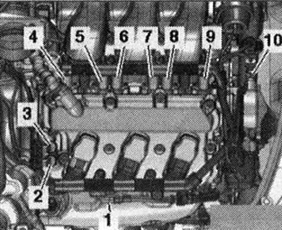
Installation location on the right bank of cylinders 1 1. Hall sensor 3 "G300"; 2. Valve of the variable valve timing system of the exhaust valves "N318"; 3. Valve 1 of the timing phase adjustment "N₂05"; 4. Executive element 6 of the timing phase regulation "F371"; 5. Executive element 5 of the timing phase regulation "F370"; 6. Executive element 4 of the timing phase regulation "F369"; 7. Executive element 3 of the timing phase regulation "F368"; 8. Executive element 2 of the timing phase regulation "F367"; 9. Executive element 1 of the timing phase regulation "F366"; 10. Hall sensor "G40"
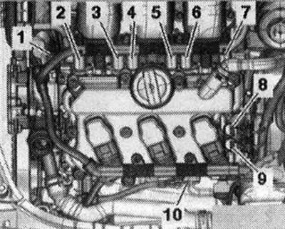
Installation locations on the left bank of cylinders 2 1. Hall sensor 2 "G1632"; 2. Executive element 7 of the timing phase regulation "3723"; 3. Executive element 8 of the timing phase regulation "3734"; 4. Executive element 9 of the timing phase regulation "3745"; 5. Executive element 10 for adjusting the timing phases "756"; 6. Executive element 11 of the timing phase regulation "767"; 7. Executive element 12 of the timing phase regulation "778"; 8. Valve 2 for adjusting the timing phases "N₂089"; 9. Valve 2 of the variable valve timing system of the exhaust valves "N319"; 10. Hall sensor "G301"
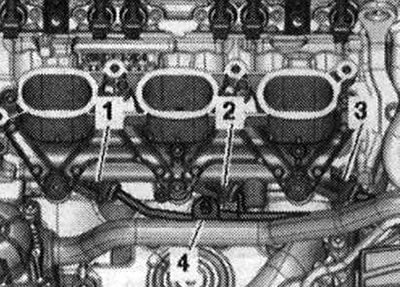
Installation locations: view from inside from right cylinder bank 1 1. Injector cylinder 1 "N30"; 2. Injector cylinder 2 "N31"; 3. Injector cylinder 3 "N32"; 4. Knock sensor 1 "G61"
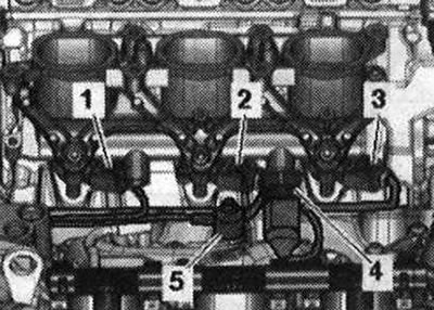
Installation locations: view from inside from left cylinder bank 2 1. Injector cylinder 6 "N84"; 2. Injector cylinder 5 "N83"; 3. Injector cylinder 4 "N33"; 4. Fuel pressure sensor "G247"; 5. Knock sensor 2 "G66"
Oil pressure regulating valve "N428"
Oil pressure sensor for low pressure "F378" "1"
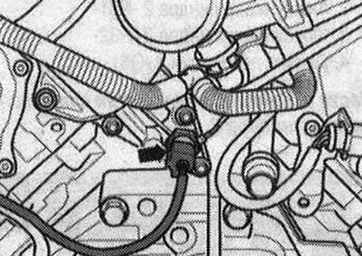
Oil pressure sensor "F22" - arrow
Installation location: front, near the engine
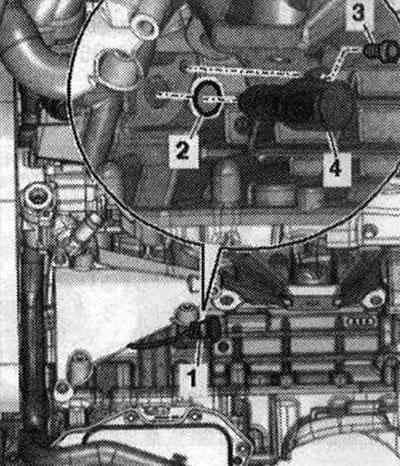
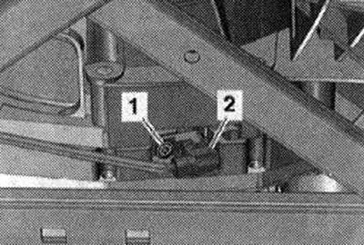
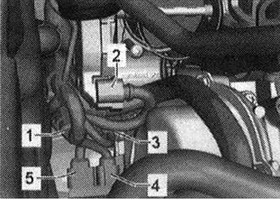
Installation location: front, near the engine 1. Coolant temperature sensor "G622"; 2. Intake manifold sequential changeover valve "N1563"; 3. Variable geometry intake manifold position sensor "G513"
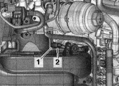
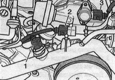
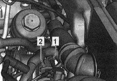
Installation locations on the fuel injection pump 1. Low pressure fuel circuit pressure sensor "G410"; 2. Fuel metering valve "N₂90"
Installation location of the engine speed sensor "G28"
Screwed to the gearbox from below
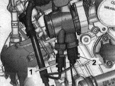
Electrical connectors 1. Knock sensor 2 "G662"; 2. Injectors of cylinder bank 2 and fuel pressure sensor "G247"
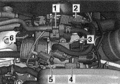
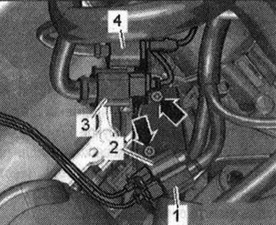
Installation location: rear, near the intake manifold 1. Used throttle valve "J3382"; 2. Electromagnetic valve 1 of the activated carbon absorber "N803"; 3. Coolant shut-off valve for Climatronic "M422" (installed only in cars without parking heater); 4. Intake air temperature sensor "C42" / intake manifold pressure sensor "Q71"
Mounting locations on rear of intake manifold (oFULEV2 toxicity standards) 1. Electromagnetic valve 1 of the absorber with activated carbon "N80"; 2. Secondary air supply control valve "N112"; 3. Intake air temperature sensor "E42" / intake manifold pressure sensor "G71"; 4. Coolant shut-off valve for Climatronic "1M422" (installed only in cars without parking heater); 5. Secondary air supply control valve 2 "N320"; 6. Used throttle valve "J338"

Electrical connectors 1. Cylinder row injectors; 2. Used throttle valve "J3383"; 3. Knock sensor "G614"; 4. Lambda probe "G395"; 5. Lambda probe after the catalytic converter "G130"
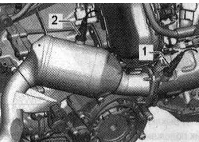
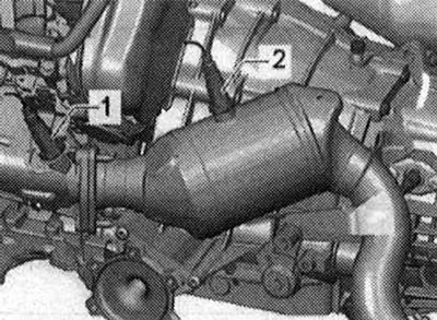
Lambda probe installation location, 1st row of cylinders 1. Lambda probe "G39"; 2. Lambda probe after the catalytic converter "G130"
Electrical connectors of lambda probes of cylinder bank 2 1. Lambda probe 2 after catalytic converter "G1312"; 2. Lambda probe 2 "G108"; 3. Injectors of cylinder bank 2 and fuel pressure sensor "G2474"; 4. Knock sensor 2 "G66"
Lambda probe installation location, 2nd row of cylinders 1. Lambda probe 2 "G108"; 2. Lambda probe 2 after catalytic converter "G131"