



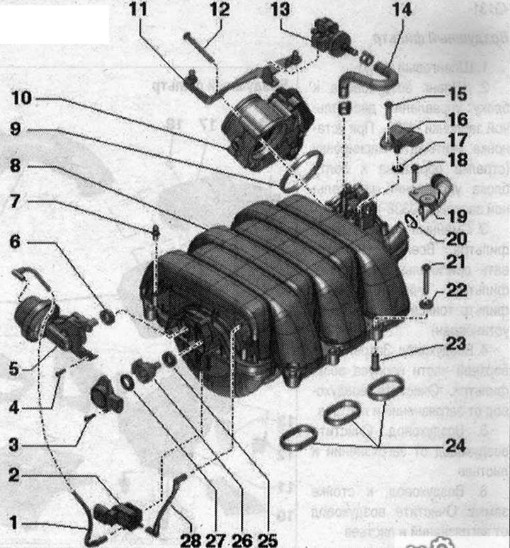
Upper part of the intake manifold 1. Vacuum hose; 2. Intake manifold sequential changeover valve "N156"; 3. Bolt for variable geometry intake manifold position sensor "G513", 2.5 Nm; 4/18. Bolt, 2.5 Nm; 5. Intake manifold geometry switching regulator. Spare part together with "pos. 26"; 6. Sealing cuff. Replace if damaged. To replace, lift with a screwdriver, press with your hand; 7. Ball pin, 2.5 Nm; 8. Upper part of the intake manifold; 9. Sealing cuff. Replace 10. Used throttle valve "J338"; 11. Bracket; 12. Bolt, 6 Nm; 13. Electromagnetic valve 1 of the absorber with activated carbon "N80"; 14. Hose; 15. Bolt, 3 Nm; 16. Intake air temperature sensor "642" / intake manifold pressure sensor "G71"; 17. Sealing ring. Replace; 19. Engine crankcase ventilation hose; 20. Sealing ring. Replace; 21. Bolt, 8 Nm; 22. Washer; 23. Bushing; 24. Gaskets. Replace; 25. Sealing cuff. Replace if damaged. To replace, lift with a screwdriver, press with your hand; 26. Lever with toothed segment for switching the intake manifold. Installation location of the toothed segment, spare part together with "pos. 5"; 27. Sealing cuff. Replace if damaged. To replace, lift with a screwdriver, press with your hand; 28. Vacuum hose
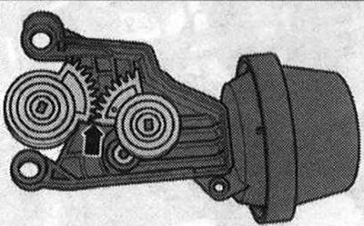
Installation location of the toothed segment of the intake manifold geometry switching flap
The lower edges of the toothed segment must be flush with each other "arrow"
(The original version is on the portal «Audimanual.ru»)