
Table of contents: Six-cylinder engine with a… ↓ Checking the operation of the… ↓ Removal the switching intake manifold ↓ Removal the intake manifold of a… ↓
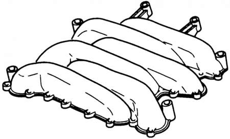
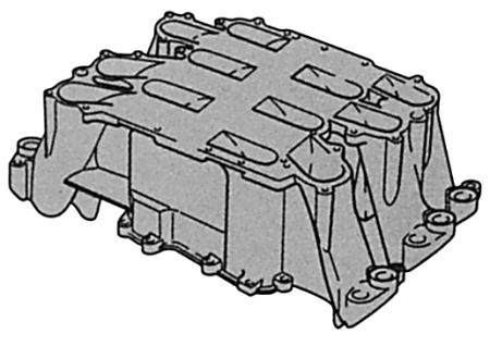
The 2.6-liter six-cylinder engine does not have a switchable intake manifold. Its intake manifold consists of the units shown here. Particular attention has been paid to the low weight of the design.

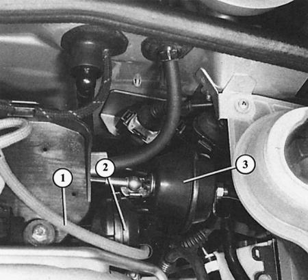
The flaps of the variable intake manifold on the 2.8-liter six-cylinder engine are actuated by a vacuum box (2) via a vacuum hose (1). This box should not be confused with the vacuum box (3) of the cruise control system (additional equipment).
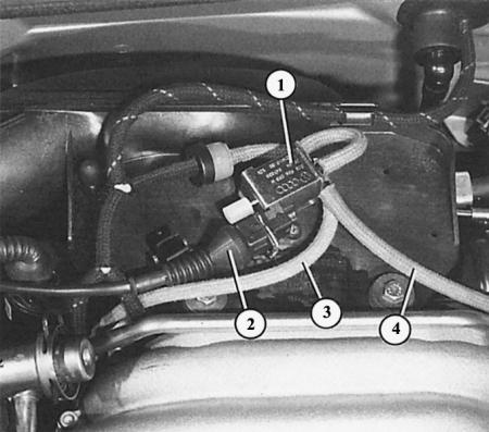
The valve (1) of the changeover of the register intake manifold determines whether there should be a vacuum in the vacuum box. It receives a signal about the changeover via the line (2) from the injection control unit. Then the vacuum from the pipe (3) of the intake manifold can move to the pipe (4) of the vacuum box. The valve is installed behind the intake manifold on the so-called noise absorber of the intake air.
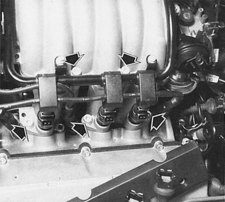
The photograph shows the intake manifold mounting bolts (arrows).
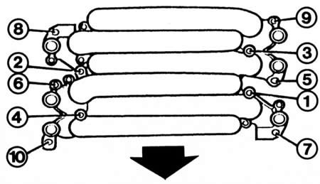
Shown here is the sequence in which the intake manifold mounting bolts of the 2.6 and 2.8 liter six-cylinder engine are tightened. This is the only way to avoid deformation of the intake manifold during installation.
Six-cylinder engine with a displacement of 2.8 liters
A long intake pipe with a small diameter ensures high torque even at low engine speeds. In contrast, a short intake pipe with a large cross-section is required to ensure high engine power at high engine speeds. In order to combine both, Audi has developed a switchable intake manifold. It closes and opens six flaps depending on the situation. This means that each cylinder has one of the intake pipes with different lengths and diameters at its disposal: either an intake manifold for torque (long tube with small diameter) or intake manifold to support power (short tube with large diameter).
All six flaps are actuated by negative pressure and are controlled depending on engine speed: up to 4,000 rpm they are closed to ensure high torque. Above 4,000 rpm they are fully open to support power. Below 4,000 rpm, the intake manifold gains up to 30 Nm of torque compared to the power intake manifold.
The 2.8-litre engine produces a maximum torque of 245 Nm at 3,000 rpm when using Euro-Super petrol (euro-Super); with super plus petrol (98 ROZ) the torque increases to 250 Nm. In a wide range from 2000 to over 5500 rpm, at least 220 Nm are available.
Checking the operation of the switching intake manifold
The intake manifold switch should only be checked if there is a lack of power. First, check the ease of movement of the lever mechanism by hand. After that, the functional ability should be checked: this is done with the engine warmed up:
1. Start the engine, raise the speed significantly above 4000 rpm.
2. Observe the vacuum box: the control rod should be pulled back.
3. If not, check the vacuum hoses for leaks. If they are OK:
4. Check the vacuum box: put the spare hose on the box connection unit, suck vigorously with your mouth.
5. If the control rod does not move and/or a lot of air can be sucked in, the box is faulty. Replace it. But if the box is in good condition:
6. Check the intake manifold changeover valve: Remove both vacuum hoses from the valve. Attach a replacement hose to the intake manifold changeover valve connector.
7. Vigorously suck on the spare vacuum hose with your mouth. No air should be sucked in (no passability).
8. Start the engine, raise the speed significantly above 4000 rpm.
9. Suck vigorously on the hose again. Air should now be sucked in (there is cross-country ability).
10. If the source of the malfunction has not yet been found (which is pretty incredible), then you need to check the settings in the workshop.
Removal the switching intake manifold
Six-cylinder engine with a displacement of 2.8 liters
1. Remove the engine cover.
2. Disconnect the spark plug connectors and remove the high-voltage wires from the brackets.
3. Remove the fuel distribution pipe together with all injection valves (section MPI/MPFI injection system).
4. Remove the inlet hose.
5. Remove the idle speed control valve or disconnect the connector.
6. Remove all vacuum hoses/crankcase vent hoses at the intake manifold and throttle body.
7. Remove the throttle cable and its potentiometer connector.
8. Loosen the bolts in the reverse order of tightening in the photo above.
9. Remove the intake manifold with the throttle valve pipe.
10. Installation: replace the gaskets.
11. Tighten the intake manifold mounting bolts according to the sequence in the figure above in four stages. Stage 1: 5 Nm, Stage 2: 10 Nm, Stage 3: 20 Nm, Stage 4: 20 Nm again.
Removal the intake manifold of a 2.6L V6
1. Dismantling is carried out in the same way as for an engine with a working volume of 2.8 liters.
2. The same rules apply to the tightening sequence of the mounting bolts as for the 2.8L engine.
[The text is based on materials from the website «AudiManual»]