
Table of contents: Checking injection nozzles ↓ Checking the fuel start valve ↓ Checking the fuel dispenser ↓ Checking the air flow meter ↓ Checking the stabilization of the… ↓ Models with 5-cylinder engine and… ↓ Checking engine temperature sensors ↓ Lambda control check (4-cylinder… ↓ Lambda control check (5-cylinder… ↓
In the following sections, we have looked at troubleshooting options that do not require any special tools or measuring devices at home. If after reading our list of faults, (at the end of the chapter) or after reading the fault memory you suspected a certain part, then here you will find the control diagram.
Note: You will find electrical diagrams further in the book, in chapter of the same name.
Checking injection nozzles
Disconnect the ignition system according to the diagram described in the chapter "Ignition system".
To check if gasoline is entering the injection system, loosen the bolts on the fuel supply line.
Don't forget a rag, because in most cases gasoline will squirt out of the fuel line. Otherwise, ask an assistant to work the starter.
If fuel is supplied, then the supply is OK. Therefore, the second thing to check is the injectors themselves.
Remove the nozzle, description see below in this chapter. To do this, the upper part of the intake manifold must first be removed.
Keep a container or rag handy to collect the fuel.
Remove the large air duct between the fuel ratio corrector and the throttle body to gain access to the shut-off valve.
Remove fuse 17 in the fuse box (chapter "Body electrical system").
Using a piece of wire (auxiliary cable), connect the positive terminal of the battery to the rear contact of the fuse box housing (in the direction of movement). The fuel pump should start working.
Raise the distributor shut-off valve slightly by hand. Now the injector should inject gasoline in a conical shape. Otherwise:
Lift the shut-off valve once until it stops. Repeat the test.
The difference in the amount of fuel injected between individual cylinders can be checked in the same way. However, this method is only suitable for lack of a better one.
Direct all four or five injectors into four or five measuring containers, respectively, without bending the fuel line hoses.
Raise it a little (about 2 cm) shut-off valve.
The assistant must maintain the said jumper until 20 cm³ (ml) of fuel has collected in the first container.
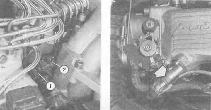
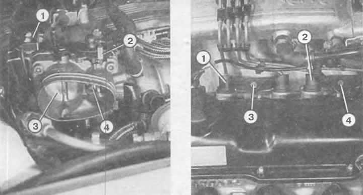
Left: Fuel starter valve (2) with connecting plug (1) in a 5-cylinder engine.
Right: Fuel start valve (arrow) in a 4-cylinder engine.
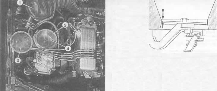
In the illustration on the left you can see the fuel mixture corrector with the shut-off valve (4), air nozzle (3), air filter (2) with the inlet hose (1) removed.
The figure on the left shows the correct position of the shut-off valve with the air nozzle. It should be exactly a = 1.9 mm below the upper edge of the narrow cylindrical part of the air nozzle. If necessary, adjust by slightly bending the spring (shown in the figure as a "snake"). Note: newer type air flow meters are equipped with an adjusting bolt instead of a spring. In this case, the position of the shut-off valve is adjusted by the said bolt.
Compare the amount of fuel injected. The difference should not be more than 2.5 cm³.
In case of large deviations, swap the injectors with the highest and lowest readings. Repeat the measurement.
If the deviations have "moved" together with the injectors, then it is time to replace the injectors with the corresponding deviations.
If you received the previous measurement results for the cylinders with deviations, then it is possible that the fuel line to the injector is narrowed or the dispenser is faulty.
Checking the tightness of the injectors: if you turn off the fuel pump after two minutes of operation with the shut-off valve raised (remove the jumper), then fuel should not come out of the injectors.
Checking the fuel start valve
Disconnect the ignition system according to the diagram described in the chapter "Ignition system".
Remove the fuel starter valve, remove the wire tip, leave the fuel line tube connected.
Work the starter a little so that the fuel pump can build up pressure.
Lower the nozzle into the container and connect two auxiliary wires to the valve contacts.
Connect the free ends of the wires to the battery terminals - one with "+", the other with "-".
The valve should now spray gasoline in a cone shape.
Check for leaks: remove auxiliary wires.
Work the starter again a little to allow the fuel pump to build up pressure
Wipe the valve clean. No gasoline should flow for a minute.
Checking the fuel dispenser
Run the engine or starter for a short time to build up full fuel pressure.
Remove the cover and the air filter element.
Remove the large air duct between the fuel mixture corrector and the throttle body.
Now you can see the shut-off valve, which must be pulled all the way up. This process must be done with the same force all the time.
When pressing the shut-off valve quickly, there should be no resistance. If there is, the air flow meter must be replaced.
If the shut-off valve can be pulled out only with great difficulty, but it goes down very easily, then the distribution piston is stuck in the fuel dispenser. Replace the fuel dispenser.
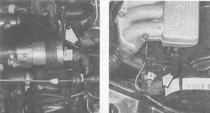
The idle speed control valve (arrow) of a 4-cylinder engine is located at the rear of the cylinder head cover (fig. on the left). The idle speed control valve for a 5-cylinder engine is located on the right front of the cylinder head (fig. on the right).
Checking the air flow meter
Warm up the engine to operating temperature or run the warm engine for about 10 seconds before checking.
After loosening the clamps, remove the air intake hose between the fuel mixture corrector and the throttle body
Check the shut-off valve: it should be located on the side facing the injection pipe, 1.9 mm below the upper edge of the narrow cylindrical part of the air nozzle, at most 3 mm deeper (see picture top left).
If the valve is not positioned correctly, it can be pulled up and its position adjusted by bending the mounting wire clip at the bottom of the air flow meter channel. Do not bend the spring under any circumstances!
Now check if the shut-off valve touches the walls.
If this is the case, the center mounting screw should be loosened and the valve re-centered.
After this adjustment, it is necessary to recheck the idle speed and CO content.
Checking the stabilization of the idle speed
Turn on the ignition, touch the distribution valve with your hand: you should feel the operating vibration, otherwise either the distribution valve or the KE-III-Jetronic injection system control unit is faulty.
Check the distribution valve: remove the plugs. Measure the resistance between the plug contacts of the distribution valve: it should be insignificant. The value "infinity" means a break in the winding - a defect in the distribution valve.
If the distribution valve is OK, then the source of the fault can be assumed to be a broken wire or a faulty control unit. Check and, if necessary, replace.
Connect the LED voltmeter to both poles of the free wire tip.
Turn on the ignition.
The voltmeter should light up, in which case the power supply from the KE-III-Jetronic injection system control unit is OK.
Checking the throttle position sensor (models with manual transmission)
The ohmmeter contacts cannot be connected directly to the sensors, one of which is located below the throttle body. Therefore, only the plug connection accessible from above is separated. The resistance in the sensor wire is measured.
Idle speed signal switch: connect an ohmmeter to pins 1 and 2 of the plug.
Throttle valve in idle position: reading 0 ohms. Slightly open the throttle valve: the reading should go to 8 ohms.
Full load signal switch: connect an ohmmeter to pins 2 and 3.
Throttle valve at full load: reading 0 ohms. Close the throttle valve slightly: the reading should go to ∞ ohms.
Models with 5-cylinder engine and automatic transmission (throttle potentiometer test)
Disconnect the three-pin plug of the throttle potentiometer,
To check, connect an ohmmeter to contacts 1 and 2:
The indicator should be 1.5-2.6 kOhm.
Now connect the ohmmeter to contacts 2 and 3:
The indicator should be 0.75-1.3 kOhm.
Slowly open the throttle valve, ohmmeter connected.
The resistance should increase to a maximum of 3.6 kOhm.
Note: The throttle potentiometer can be adjusted. However, after this, a "basic adjustment" of the automatic transmission must be performed - a job for a workshop.
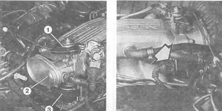
Left: Throttle body of a 4-cylinder engine with the air intake hose removed.
1 - gas thrust eccentric;
2 - throttle valve;
3 — throttle position sensor.
Right: The throttle position sensor plug connection is located on the 4-cylinder engine on the left side of the intake manifold (arrow).
With the air intake hose removed in a 5-cylinder engine, both throttle valves (3 and 4) can be seen in the throttle body. On top of the unit is a drive rod system (2), which opens first one, and then the second throttle valve when the accelerator pedal is pressed further. Position (1) represents the idle speed signal switch.
Right: for removing injection nozzles (4-cylinder engine) unscrew the mounting bolts (3 and 4), remove the injector fasteners (holders) (1 and 2), remove the injection nozzles.
Checking engine temperature sensors
The vehicle with a 5-cylinder engine and the KE-III-Jetronic injection system is equipped with a dual temperature sensor for the injection system and a fully electronic ignition system. The measurements of these sensors are made from each of the two contacts to the "ground" (cylinder block). In a 4-cylinder engine, measurements are taken between both contacts.
4-cylinder engine: Connect an ohmmeter to both plug contacts of the temperature sensor.
5-cylinder engine: connect an ohmmeter to one of the two terminals and to ground.
For all: the obtained resistance value depends on the temperature.
You can check from the diagram on the next page whether the received sensor readings are within the correct range.
Lambda control check (4-cylinder engine)
Checking the lambda probe power supply: disconnect the lambda probe plug connection.
Connect the voltmeter to both plug contacts of the control unit wire.
Start the engine: if voltage is present, then the lambda probe power supply is OK. Otherwise, check the wiring.
Checking the lambda probe heating: connect the ohmmeter and the lambda probe wire to both plug contacts.
If the heating is working properly, the readings should be 3-15 Ohm. If the readings are different, the lambda probe should be replaced.
Checking the lambda probe signal: disconnect the wire, connect a voltmeter between the wiring to the control unit and the ground (housing).
Turn on the ignition. The indicator should be 400-700 mV.
Otherwise, check the wiring.
To check the probe, connect an ohmmeter between the engine ground and the probe signal wire.
The normalized reading is ∞ Ohm. Otherwise the probe is faulty.
Lambda control check (5-cylinder engine)
Although checking the lambda control function can be done relatively easily, it requires a matching wire and an ammeter, which many electronics enthusiasts have. Or you can check with a CO analyzer. The test is described below:
Warm up the engine.
Remove the pressure regulator plug, connect the measuring adapter you made from two suitable plugs and a piece of wire, connecting the wiring and the pressure regulator.
Separate one of the matching wires and connect it to the measuring device (milliampere range).
Start the engine and let it idle.
Record the obtained value.
Pull out the oil dipstick.
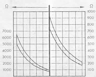
The diagram shows the resistance value of the coolant temperature sensor depending on the temperature. (See the next picture)
The current in the control circuit must increase.
Otherwise, one of the components of the lambda control is faulty.
In this case, try to separate the plug connection to the lambda probe and hold the green wire to the control unit for about 20 seconds on the ground.
If the current in the control circuit now changes, then the KE-lll-Jetronic injection system control unit is OK, but the lambda probe is faulty - replace it.
If nothing happens, then the injection system control unit is faulty.
Note: The basic prerequisite for a functioning lambda control is a correct basic idle setting, which means that the CO content is within the norm, otherwise the control will be constantly at one end of the normative range. The same conditions are created if the mixture is heavily depleted by unaccounted air.
The original article is available on the online resource AUDIMANUAL.ru