
Table of contents: Removal injection nozzles ↓ Removal the air intake sleeve ↓ Removal the air intake sleeve ↓ Removal the upper part of the intake… ↓
For many components of the injection system, no additional descriptions of disassembly are required. Where explanations are necessary, you will read them in the following sections.
Removal injection nozzles
5-cylinder engine: Remove the upper part of the exhaust manifold.
For all: unscrew the fasteners of the injection nozzles.
Use pliers to pull out the nozzle together with the attachment.
The fuel line remains connected to prevent dirt from getting into the injector.
When installing, it is necessary to moisten the rubber sealing rings of the injector and the liners with gasoline to ensure easy installation on the sealing surface.
If the injector is installed "dry", there is a risk that the rubber ring will flatten and will not seal properly. This will result in engine malfunctions due to unaccounted air, such as uneven idle operation.
Damaged or cracked sealing rings must be replaced.
Tighten the injector mounting bolts to 10 Nm.
Removal the air intake sleeve
The thick sleeve between the fuel mixture corrector and the throttle body must be removed, at least partially, during various repairs to the injection system:
Loosen the clamps on the fuel mixture corrector and the throttle body.
Loosen the clamps of the remaining air duct hoses on the air intake sleeve. These include: the hose to the idle speed stabilization control valve, to the air duct of the injection nozzles, etc.
Removal the air intake sleeve
Remove the air duct hoses.
Remove the air intake sleeve.
When installing, insert the grid above the fuel mixture corrector with the convex side facing up. Pay attention to the "oben" (top) mark.
Removal the upper part of the intake manifold
Remove the air intake sleeve.
Disconnect the gas drive cable and remove it from the counter support.
Remove the throttle position sensor plug.
Remove the air duct hoses.
Loosen the inner flange bolts.
Remove the exhaust manifold.
When installing, be sure to use new flange gaskets.
Tighten the flange mounting bolts in two passes to a final torque of 20 Nm.
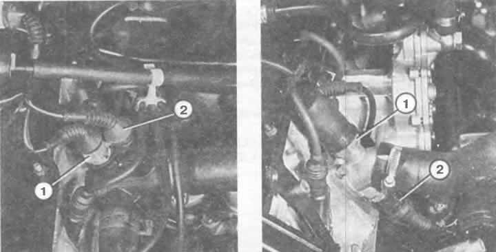
Left: On a 4-cylinder engine, the injection temperature sensor (1) and the coolant temperature sensor (2) and warning light are located at the top in the hose fitting on the cylinder head.
Right: In a 5-cylinder engine, the injection temperature sensor (2) is located at the bottom in the hose fitting, the electronic temperature sensor (1) (more about this in the chapter "Instruments and tools") is screwed on top in the fitting of the coolant pipe.
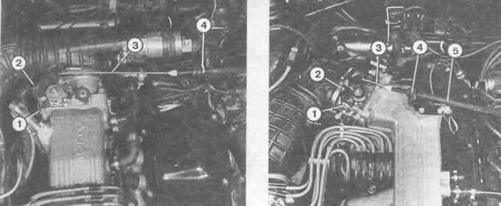
Right: In a 5-cylinder engine, the gas rod is also installed. Designation: 1 and 2 - mounting brackets; 3 - gas traction; 4 — counter support of the guide fastening; 5 — gas thrust shell.
Left: The throttle cable (3) of a 4-cylinder engine is secured with two mounting brackets (1 and 2) to the eccentric of the throttle lever. The throttle cable is shown together with the guide fastener (4).