
Table of contents: Electronic control unit ↓ Throttle control unit ↓ Pressure regulator ↓ Injection valves ↓ Intake air temperature sensor ↓ Coolant temperature sensor ↓ Fresh air flow meter ↓
Electronic control unit
The control unit in the electronic box receives information via a multi-pin connector:
- starter, terminal 50 start and end of the starting process;
- throttle potentiometer, its current position;
- hall sensor of the ignition system for regulating the engine speed;
- lambda probe in a catalytic converter for measuring the residual oxygen content in exhaust gases;
- intake air flow meter;
- intake air temperature sensor (only in 110 kW turbo engine);
- coolant temperature sensor in the coolant supply pipe behind the cylinder head;
- knock sensor I on the engine block during "knock" combustion;
- knock sensor II (only in engines with a working volume of 1.8 l) also on the engine block for precise localization of detonation combustion.
Based on the information on the engine speed and the pressure in the intake manifold, the control unit calculates the duration of the opening of the electromagnetically actuated injectors and, accordingly, the amount of fuel to be injected. For this purpose, the control unit is provided with engine data, which is a collection of data on all conceivable engine situations, the amount of fuel required for each situation and the corresponding ignition timing. The control unit can also vary the data after receiving so-called correction signals (for example, intake air and coolant temperature).
Throttle control unit
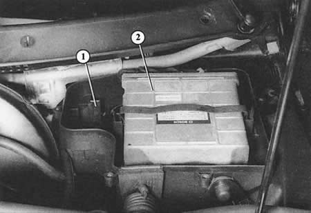
The ignition/injection system control unit (2) is located in the electronic box on the left rear of the engine compartment (in the so-called humidification tank). In the bracket (1) next to the control unit there is a place for the height sensor for the turbo engine.
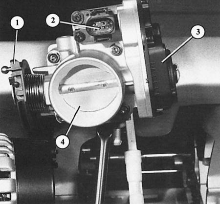
Throttle control unit in a turbo engine with a working volume of 1.8 l: 1 - throttle lever; 2 – connection unit for the power supply of the control unit (3) of the throttle valve; 4 – throttle valve.
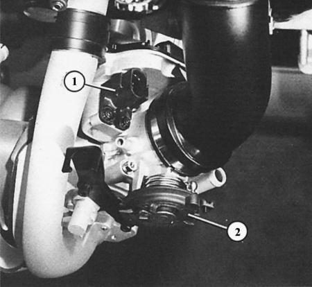
The throttle control unit in the 1.6L engine is basically identical to the 1.8L engine unit, although its mounting position is different. The numbers indicate: 1 – power supply connection unit; 2 – throttle lever.
The so-called throttle control unit combines three separate units, known from other injection systems as functional units.
Throttle valve. It is connected by a cable to the pedal in the cabin and doses the flow of fresh air into the engine. The more the gas pedal is pressed, the more the throttle valve opens; at full throttle it is completely open.
Throttle Potentiometer The throttle potentiometer determines the current throttle position in the range from idle (throttle valve closed) to full throttle (throttle valve is fully open). Based on its information, the idle speed stabilization valve, also integrated into the throttle valve pipe, is activated, the traction is cut off or the mixture is enriched at full load.
Idle speed stabilization valve. It lets in a metered additional amount of air into the intake ducts behind the throttle valve during the engine warm-up stage, when the servo control is fully turned, when the air conditioning system is running or the automatic transmission stage is set. The increased air flow in the direction of the intake manifold is detected by the fresh air flow meter and, as a result, causes an increased fuel supply. This reduces the increased friction in a cold engine or under increased engine load due to the servo pump, air conditioning compressor or automatic transmission, which take power from the engine.
Pressure regulator
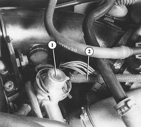
The fuel pressure regulator (1) is connected to the throttle valve pipe via a vacuum hose (2). It regulates the pressure in the system by increasing or decreasing the fuel recirculation.
It is located in the fuel distributor and regulates its pressure on the injectors. To do this, it is given information about the level of low pressure in the intake manifold. At idle, with the throttle valve closed and very low pressure, it maintains a lower pressure. As the pressure drops under increased engine load, the pressure regulator increases the fuel pressure. The fuel pump creates a much higher operating pressure, but the return of gasoline to the fuel tank is increased or decreased accordingly by means of the pressure regulator.
Injection valves
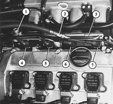
The injection valves (4–7) are located in the direction of travel on the left side of the cylinder head in the intake manifold. The following numbers indicate: 1 – fuel pressure regulator; 2 – fuel supply line; 3 – fuel distribution pipe.
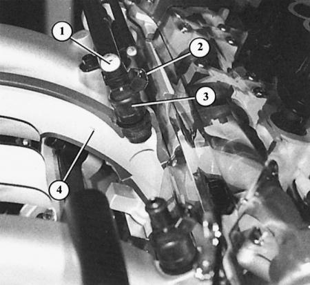
In this model, in section, it is visible that each injection valve (3) injects into the intake pipe (4). Fuel is supplied to it from the distribution pipe (1), the signals for injection go through the cable connection (2) to the control unit.
At each revolution of the crankshaft, they inject gasoline into the suction channel in front of the inlet valve of the corresponding cylinder - the duration is determined by the control unit.
Intake air temperature sensor
In the case of a 110 kW turbo engine, it is located in the air intake hose and can accurately measure the temperature of the air supplied by the turbocharger. The temperature information is sent to the control unit as a resistance value. It is used for optimal fuel dosing. A hot turbocharger, depending on the operating state, strongly heats the intake air.
Coolant temperature sensor
Coolant temperature is used to control several injection functions: enrichment of the fuel-air mixture during cold engine start, post-start enrichment (across the entire temperature range), when enriched during acceleration and when the traction is switched off. Information about the coolant temperature is also transmitted to the control unit in the form of a resistance value. It calculates the correct injection time, which in a warm engine is from 2 to 8 ms. This value can increase by almost 70% when the temperature drops to the arctic level of -25°C.
Fresh air flow meter
In the flow of the intake air there is an electrically conductive plate, which is heated electrically. Depending on the amount of intake air, its flow changes, which cools the plate more or less. The change in temperature causes a change in the electrical resistance of the conductor. This measured value is used by the control unit.
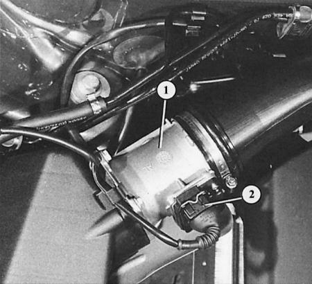
At the rear right in the engine compartment of the naturally aspirated engine with a displacement of 1.6 and 1.8 liters, there is a fresh air flow meter (1), flanged to the air filter housing. The number "2" shows the connection connector. In the turbo engine with a displacement of 1.8 liters, the fresh air flow meter is located inside the air filter housing.